Method and circuit for generating a tracking error signal using differential phase detection

a technology of phase detection and tracking error, applied in the direction of recording signal processing, head disposition/mounting, instruments, etc., to achieve the effect of increasing the accuracy of tracking locking and stability, and improving the phase variation caused by the circui

Active Publication Date: 2005-01-20
TIAN HLDG
View PDF4 Cites 14 Cited by
  • Summary
  • Abstract
  • Description
  • Claims
  • Application Information

AI Technical Summary

Benefits of technology

To conclude the foregoing, in a traditional tracking error circuit frame, the variation of a signal can easily influence the phase difference and make tracking offset and cause locking track point to be offset. In an improved tracking error circuit frame, the phase leading and the phase delay by the circuit still influence the tracking signal. As a result, the present invention provides a tracking error signal using a differential phase detector frame and uses the same phase difference signals to inter-eliminating phase difference for improving phase variation caused by the circuit. Furthermore, it reduces the non-physically produced phase lock point to be offset and increases the accuracy of track locking and stability of tracking.

Problems solved by technology

In view of prior art, there are many disadvantages in traditional tracking error circuit.

Method used


Image

  • Method and circuit for generating a tracking error signal using differential phase detection
  • Method and circuit for generating a tracking error signal using differential phase detection
  • Method and circuit for generating a tracking error signal using differential phase detection

Examples


Embodiment Construction

In the following, some preferred embodiments of the invention would be described in greater detail. Nevertheless, it should be recognized that the present invention could be practiced in a wider range in other embodiments beside those explicitly described, and the scope of the present invention is not limited by these expressed embodiments but specified in the accompanying claims.

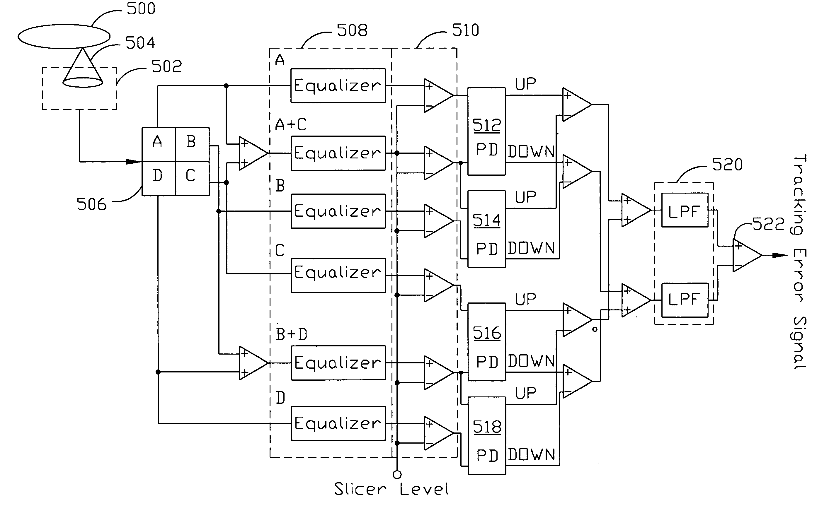
A preferred embodiment of the present invention is a circuit for generating a tracking error signal using a differential phase detection, which comprises, a quadrant photodetector for receiving an optical signal and generating splitting signal A, splitting signal B, splitting signal C and splitting signal D, wherein splitting signal A and splitting signal C being added by an adder to form a group signal (A+C) and splitting signal B and splitting signal D being added by another adder to form another group signal (B+D). A plurality of equalizers for receiving, equalizing and amplifying the splitting signal...


PUM

PropertyMeasurementUnit
differential phase detectionaaaaaaaaaa
phaseaaaaaaaaaa
frequencyaaaaaaaaaa

Abstract

A circuit for generating tracking error signal using differential phase detection, comprising a quadrant photodetector for receiving optical signal and inducting splitting signal A, splitting signal B, splitting signal C and splitting signal D, two adders for generating group signal (A+C) and group signal (B+D). A plurality of equalizers for receiving, equalizing and amplifying splitting signal A, splitting signal B, splitting signal C, splitting signal D, group signal (A+C) and group signal (B+D). A plurality of phase detectors for receiving the output of equalizers and comparing phase difference of splitting signal A and group signal (A+C), group signal (A+C) and splitting signal B, splitting signal C and group signal (B+D), and group signal (B+D) and splitting signal D, and outputting a plurality of adjustment signals respectively. A circuit for eliminating the phase difference by adding and subtracting some adjustment signals with same phase difference. A comparator for receiving and comparing the output of the circuit to obtain a tracking error signal.

Description

BACKGROUND OF THE INVENTION 1. Field of the Invention The present invention generally relates to the processing of a tracking error signal in disk server system, and more particularly, to a method for generating a tracking error signal using a differential phase detection circuit. 2. Description of the Prior Art Generally speaking, a pickup head is used in an ordinary optical pickup system to read data recorded on the disk tracks. Normally, there are many tracks on a disk and the pickup head moves between different tracks to read the data, the action of which is called cross-track motion. After the cross-track motion, pickup head needs and re-lock the track in order to read the data stably. When the pickup head cannot properly lock the track and read the data along the track, a tracking error is thus produced and the data cannot be read correctly. FIG. 1 shows block diagram for generating DVD tracking error signal in a traditional disk system. Through the lens 104, the pickup he...

Claims


Application Information

Patent Timeline
Patent Type & Authority Applications(United States)
IPC IPC(8): G11B7/09G11B20/14
CPCG11B7/0906G11B7/0943G11B2220/2562G11B20/10046G11B20/10342G11B20/10009
Inventor LAI, YI-LINWANG, SAGA
Owner TIAN HLDG
Why Eureka
Try Eureka