[0016] The invention has been devised to overcome the above-described problems, and an object of the invention is to provide a projector which is capable of suppressing a decline in luminance and breakage of the light source lamp ascribable to the positional offset of the lamp case or the light source lamp.
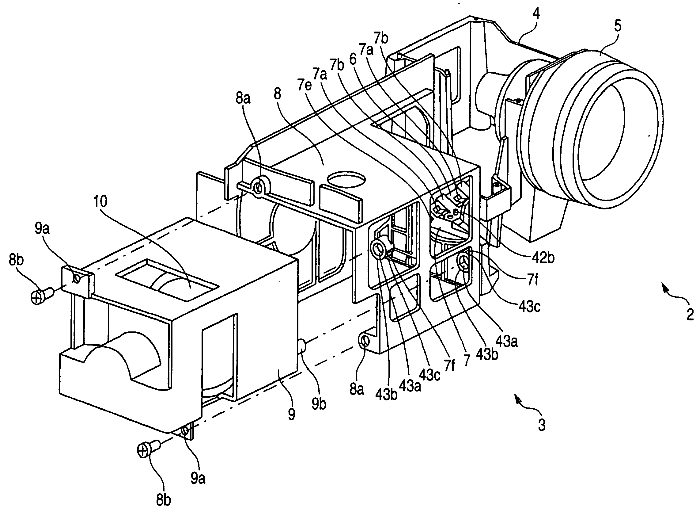
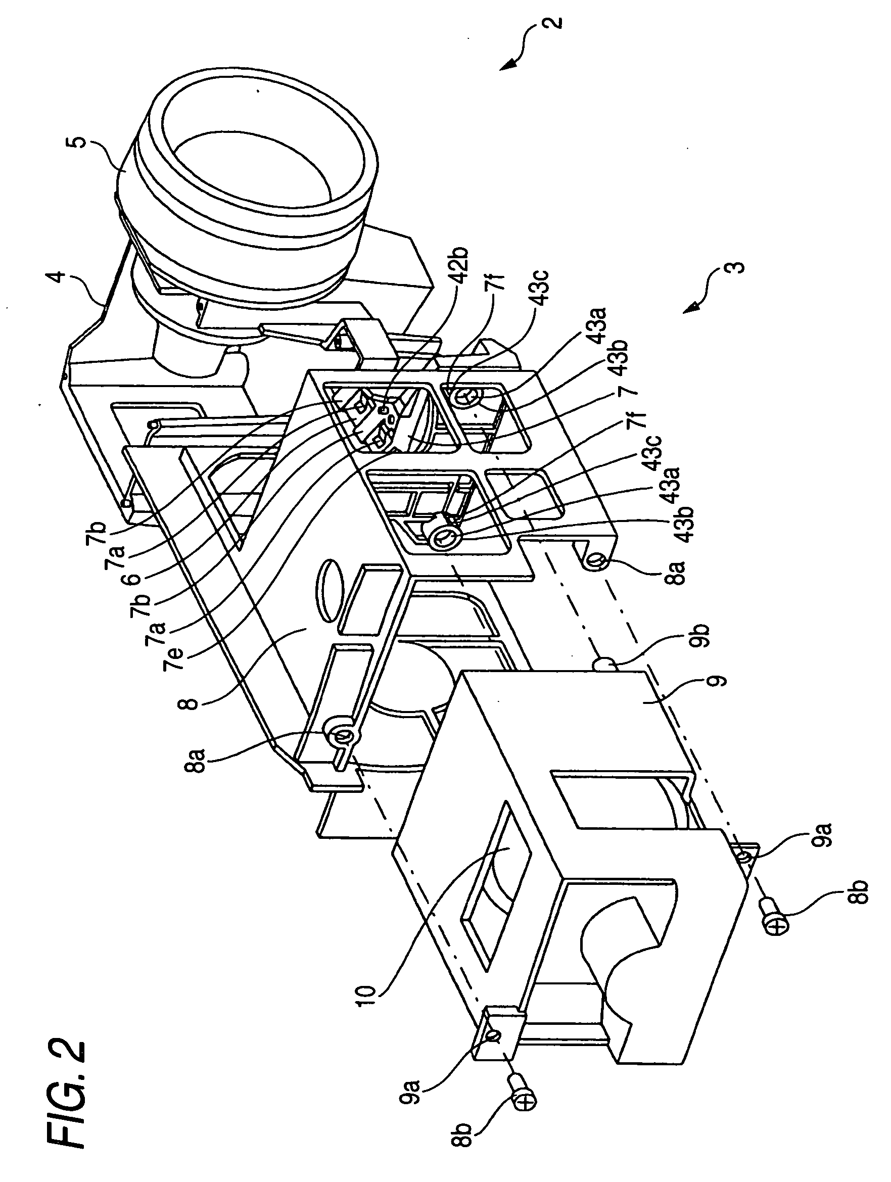
[0018] In the projector according to the above-described first aspect, the plurality of detent members are provided at positions respectively corresponding to the plurality of guide holes of the optical part holder, and the slot portions into which the detent members are inserted are respectively provided in the plurality of cylindrically shaped portions provided on the optical part holder and having the guide holes, as described above. At the same time, the concave engaging portions, for engaging the detent members inserted in the slot portions of the cylindrically shaped portions when the positioning bosses are inserted in the guide holes of cylindrically shaped portions of the optical part holder, are respectively provided in the plurality of positioning bosses of the lamp case. Thus, in a case where the lamp case with the light source lamp fitted therein is replaced, as the detent members and the concave engaging portions of the positioning bosses of the lamp case are engaged with each other, the lamp case can be temporarily fixed in a state of being positioned with respect to the optical part holder. For this reason, even if the lamp case has not been completely fixed with screws, the lamp case is not offset. As a result, since the
optical axis of the light source lamp fitted in the lamp case is also not offset, it is possible to prevent the emergent light from the light source lamp from entering a region other than an inlet portion of the light tunnel. As a result, it is possible to suppress a decline in luminance, and prevent the light source lamp from breaking due to the fact that the emergent light from the light source lamp which entered the region other than the inlet portion of the light tunnel is reflected toward the light source lamp side. In addition, since the lamp case is temporarily fixed when the lamp case is fixed with the screws, the operation of replacing the lamp case can be performed easily. It should be noted that in the case of replacing the lamp case of the projector installed on a ceiling, at the time of the operation of fixing the lamp case with the screws, the lamp case can be prevented from dropping by virtue of the temporary fixation by the detent members and the concave engaging portions. Therefore, the invention is particularly effective.
[0019] In addition, in the projector according to the first aspect, since the detent member is constructed to be resiliently deformable, at the time of inserting the positioning boss of the lamp case into the guide hole of the cylindrically shaped portion of the optical part holder, the detent member is resiliently deformable when the positioning boss abuts against the detent member. Hence, the positioning boss can be inserted sufficiently into the guide hole. In consequence, the concave engaging portion of the positioning boss and the detent member can be easily engaged with each other. In addition, since the detent member is constructed to be substantially U-shaped, the resistance which the positioning boss receives from the detent member can be reduced when the positioning boss of the lamp case is inserted into the guide hole of the cylindrically shaped portion of the optical part holder. In consequence, the positioning boss can be easily inserted into the guide hole, and the concave engaging portion of the positioning boss and the substantially U-shaped detent member can be easily engaged with each other. In addition, the slot portion, which extends from the outer
peripheral surface of the cylindrically shaped portion to the guide hole and into which the detent member is inserted, is provided in the cylindrically shaped portion of the optical part holder. Therefore, the detent member can be easily engaged with the concave engaging portion of the positioning boss of the lamp case inserted in the guide hole of the cylindrically shaped portion. Furthermore, since the detent members are integrally provided on the light-tunnel fixing member, even if the detent members are provided, the number of parts does not increase.
[0021] In the projector according to the above-described second aspect, the detent member is disposed at a position corresponding to the guide hole of the optical part holder, and the concave engaging portion, which engages the detent member when the positioning boss is inserted in the guide hole of the optical part holder, is provided on the positioning boss of the lamp case, as described above. Thus, in the case where the lamp case with the light source lamp fitted therein is replaced, as the detent member and the concave engaging portion of the positioning boss of the lamp case are engaged with each other, the lamp case can be temporarily fixed in a state of being positioned with respect to the optical part holder. For this reason, even if the lamp case has not been completely fixed with screws, the lamp case is not offset. As a result, since the
optical axis of the light source lamp fitted in the lamp case is also not offset, it is possible to prevent the emergent light from the light source lamp from entering a region other than the inlet portion of the light tunnel when the form of the emergent light from the light source lamp is shaped by the light tunnel. As a result, it is possible to suppress a decline in luminance, and prevent the light source lamp from breaking due to the fact that the emergent light from the light source lamp which entered the region other than the inlet portion of the light tunnel is reflected toward the light source lamp side. In addition, since the lamp case is temporarily fixed when the lamp case is fixed with the screws, the operation of replacing the lamp case can be performed easily. It should be noted that in the case of replacing the lamp case of the projector installed on a ceiling, at the time of the operation of fixing the lamp case with the screws, the lamp case can be prevented from dropping by virtue of the temporary fixation by the detent member and the concave engaging portion. Therefore, the invention is particularly effective.

