Optical substrates having light collimating and diffusion structures
- Summary
- Abstract
- Description
- Claims
- Application Information
AI Technical Summary
Benefits of technology
Problems solved by technology
Method used
Image
Examples
experiment b
[0123]
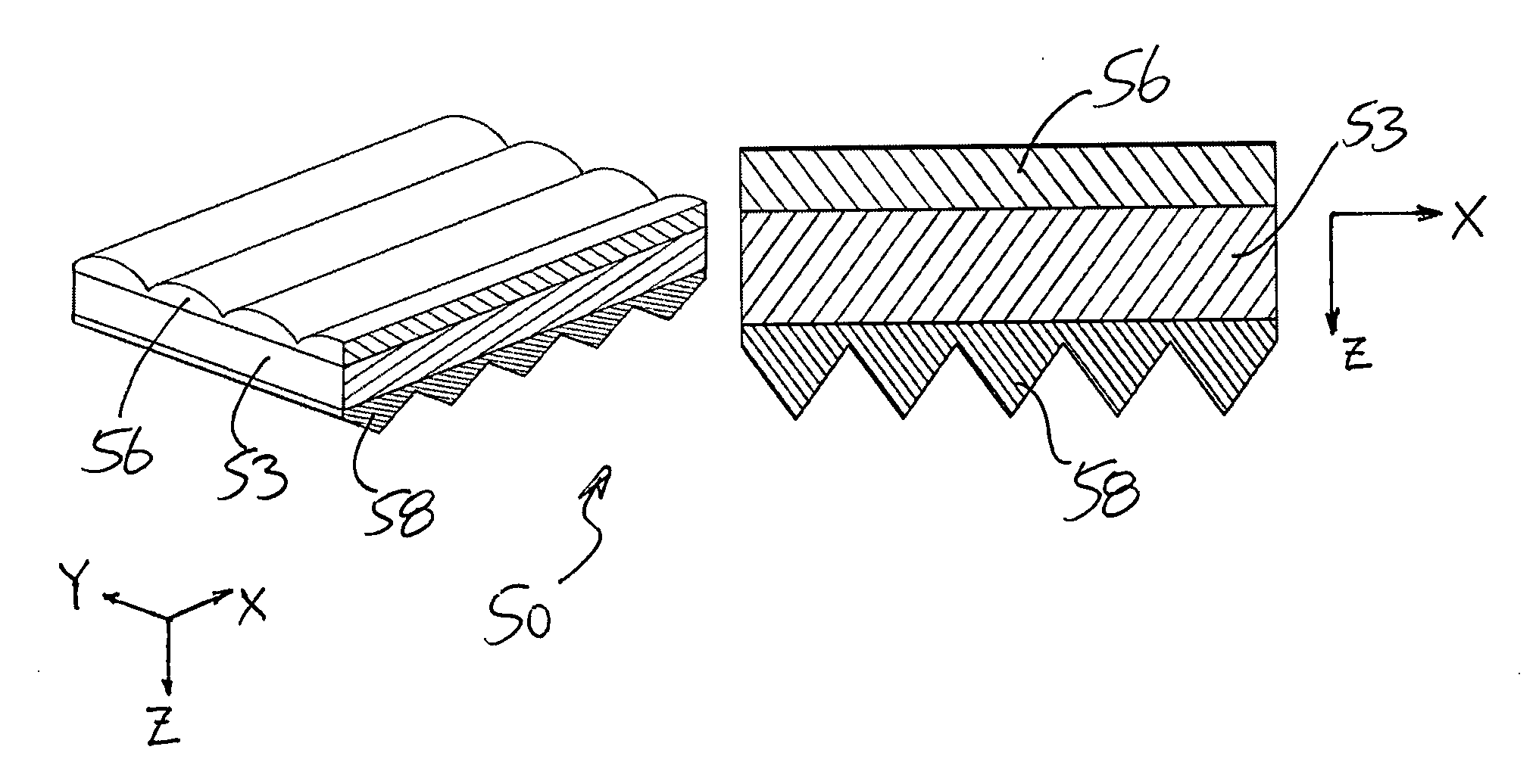
[0124]Table 2 shows the effects of the refractive index of the lenticular structure (e.g., structure shown in FIGS. 6a and 8 with zero flat ratio). At bigger angles θ, haze is higher but gain is lower. Haze will increase when the refractive index of lenticular structure increases. However, the gain of optical substrate will decrease. It appears that the preferred refractive index of lenticular structure is in the range of 1.45 to 1.58.
TABLE 2Haze(single sidelenticularstructure withLenticular structureFlatno prismGainRadiusAngle θRefractiveAngle αratiostructure)(with prism structure onDark and bright(μm)(deg.)Index(deg.)%%the light output side)fringes58821.5690087.21.34Not observed58661.5690075.71.48Not observed58521.5690071.81.51Not observed58361.5690063.01.51Not observed58821.4890078.21.42Not observed58661.4890072.91.51Not observed58521.4890068.41.53Not observed58361.4890058.01.53Not observed
experiment c
[0125]
[0126]Table 3 shows there is no significant change in haze and gain while changing lenticular radius (e.g., structure shown in FIGS. 6a and 8 with zero flat ratio). However, angle θ is significant to changes in haze and gain.
TABLE 3Haze(single sidelenticularstructure withLenticular structureFlatno prismGainRadiusAngle θRefractiveAngle αratiostructure)(with prism structure onDark and bright(μm)(deg.)Index(deg.)%%the light output side)fringes7.81061.4890077.21.35Not observed231061.4890081.51.34Not observed581061.4890079.11.25Not observed7.8661.4890070.51.51Not observed23661.4890070.01.51Not observed58661.4890072.91.51Not observed7.8361.4890029.31.55observed23361.4890050.91.54Not observed58361.4890058.01.53Not observed
experiment d
[0127]
[0128]Table 4 shows the effects of the flat ratio of the optical substrate, such as embodiment shown in FIG. 9. At low flat ratio, the optical substrate has higher haze and interference fringes may be eliminated. When the flat ratio of the optical substrate is higher, the ability to eliminate the interference fringes decreased. The preferable flat ratio of the optical film does not exceed 10%.
TABLE 4Haze(single sidelenticularstructure withLenticular structureno prismGainRadiusAngle θRefractiveAngle αFlat ratiostructure)(with prism structure onDark and bright(μm)(deg.)Index(deg.)%%the light output side)fringes581061.48907.7674.71.27Not observed581061.489034.7061.41.34Observed581061.489061.6450.81.37Observed
[0129]Experiment E:
[0130]In this experiment, the two optical substrates are rotated with respect to one another to vary the angle α (see embodiment of FIG. 6a). Table 5, the angle α can be substantially 90° to provide a brightness enhancement film having acceptable diffusion ...
PUM
 Abstract
Description
Claims
Application Information
 - R&D
- Intellectual Property
- Life Sciences
- Materials
- Tech Scout
- Unparalleled Data Quality
- Higher Quality Content
- 60% Fewer Hallucinations
Browse by: Latest US Patents, China's latest patents, Technical Efficacy Thesaurus, Application Domain, Technology Topic, Popular Technical Reports.
© 2025 PatSnap. All rights reserved.Legal|Privacy policy|Modern Slavery Act Transparency Statement|Sitemap|About US| Contact US: help@patsnap.com


