Light emitting display

a technology of light-emitting displays and displays, applied in the field of displays, can solve the problems of insufficient contrast ratio of displayed images, inability to return to the ambient, and inability to view displayed images, etc., to achieve the effect of reducing power consumption, displaying images more efficiently, and maintaining high contrast ratio

Active Publication Date: 2005-02-17
SAMSUNG DISPLAY CO LTD +1
View PDF4 Cites 111 Cited by
  • Summary
  • Abstract
  • Description
  • Claims
  • Application Information

AI Technical Summary

Benefits of technology

Moreover, the patent documents (3), (4) and (5) disclose a method for realizing a circular polarizer having a broad wavelength band and, at the same time, high antireflection effect in a wide viewing angle range by use of a laminate of biaxial phase difference films. Use of the circular polarizer can realize an OLED display of high contrast ratio in a wide viewing angle range.
In other words, the present invention can realize a light emitting display which produces a brighter image or an image at a lower power consumption, and, at the same time, keeps a high contrast ratio and controls color changes in a wide viewing angle range.

Problems solved by technology

In the above structure, however, the reflective electrode works as a mirror while light is not emitted to catch ambient scenes, making it hard to view displayed images.
The displayed image may have an insufficient contrast ratio when incident light passing into the OLED display from an ambient atmosphere (hereinafter sometimes referred to as “ambient light”) is reflected, because a black image may not be sufficiently dark.
Therefore, light transmitted by the quarter-wave plate is absorbed by the polarizer and cannot be returned back to the ambient.

Method used


Image

  • Light emitting display
  • Light emitting display
  • Light emitting display

Examples


Embodiment Construction

The embodiments of the present invention are described by EXAMPLES and the drawings.

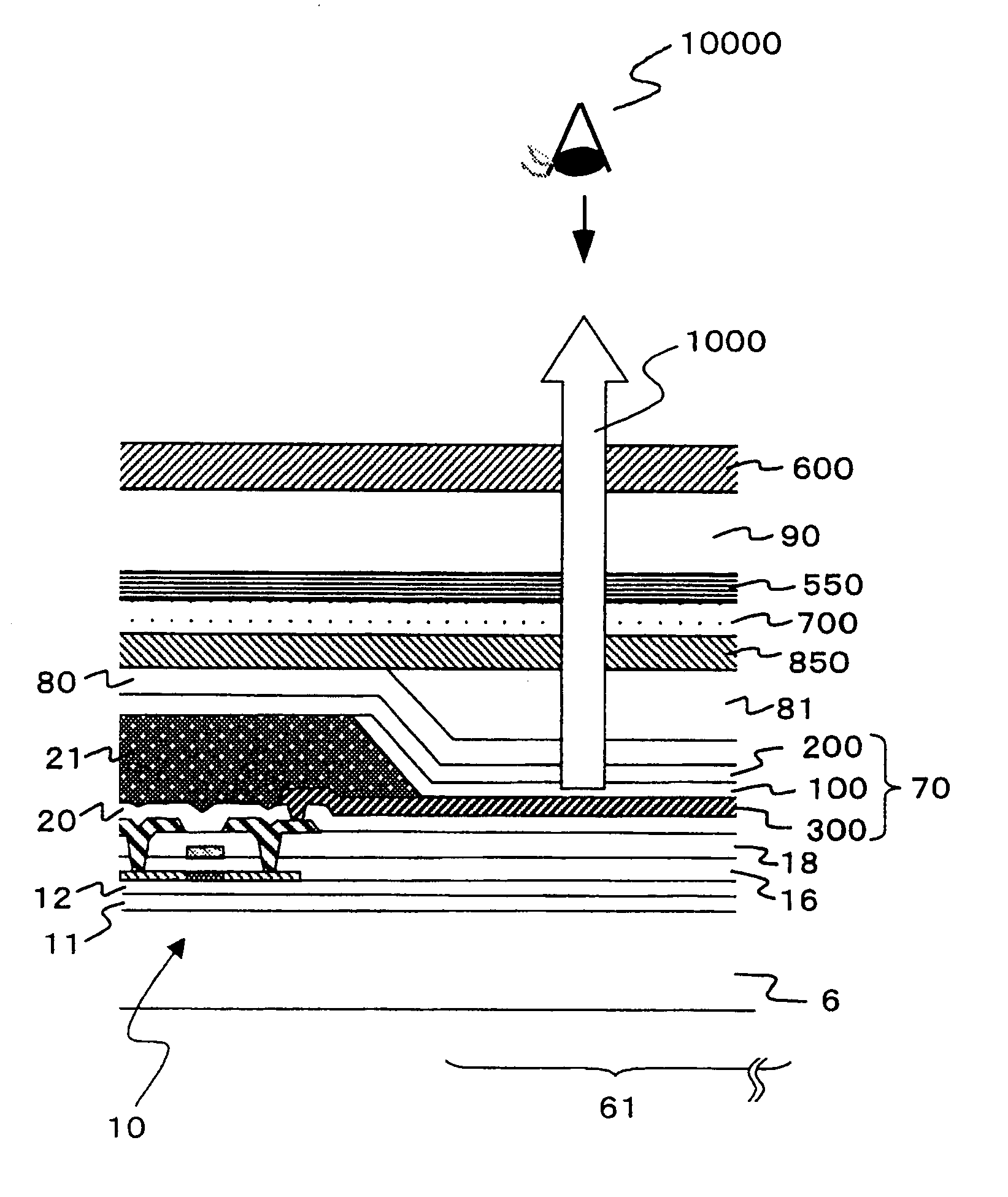
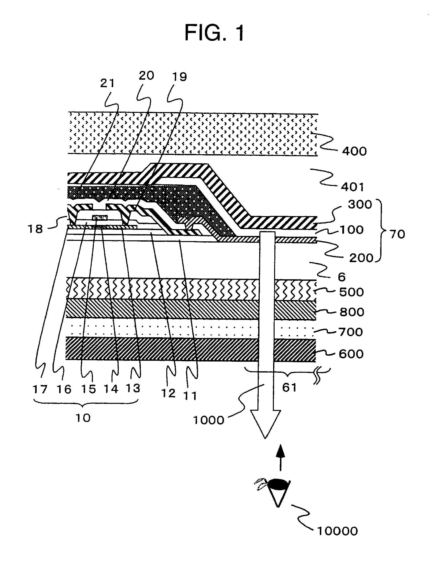
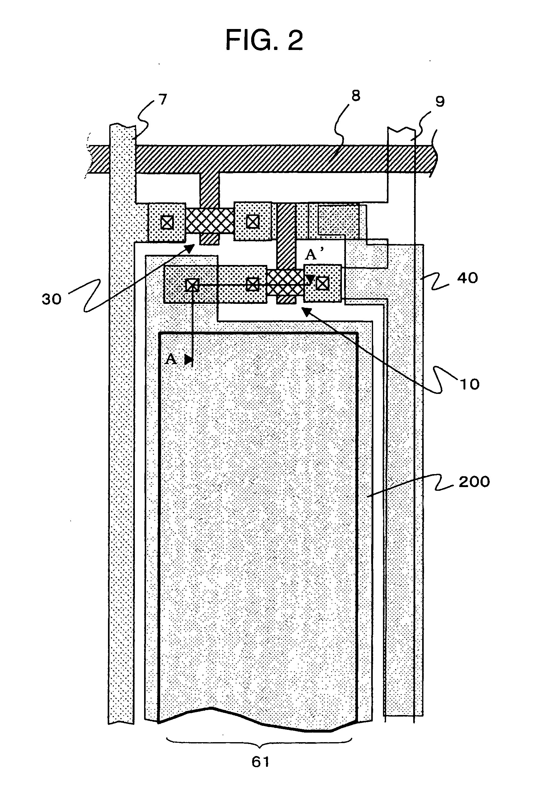
FIG. 1 is a cross-sectional view of one pixel and its periphery which illustrates the structure of one embodiment of the light emitting display of the present invention. FIG. 2 is a partly perspective diagram which illustrates the structure of the pixel area for the light emitting display of the present invention. This embodiment of the light emitting display is an active matrix drive type OLED display having a thin-film transistor as a switching device and organic light-emitting diode.

The present invention is described by taking an active matrix drive type as an example, which by no means limits the present invention.

FIG. 3 is a block diagram which schematically illustrates the overall layout of the light emitting display 1, and FIG. 4 shows an equivalent circuit of the active matrix provided in its display area 2.

Referring to FIG. 3(a), the light emitting display 1 has the display area 2 pos...


PUM


Abstract

The present invention provides light emitting displays which produce a bright image by efficiently emitting light radiated from a light-emitting thin-film layer to the viewer side, and also produces a high-quality image of high contrast ratio and changing in color to a limited extent over a wide viewing angle range even in a bright atmosphere. The light emitting displays are provided with a plurality of light-emitting devices 70, each device 70 having a light-emitting thin-film layer 100 and a light reflective surface 300 in this order on the back side, and a circularly polarized light reflective layer 500 which separates incident light into two types of circularly polarized components, one being reflected and the other transmitted by the reflective layer, an optical compensation layer 800, a quarter-wave plate 700 and a polarizer 600 on the front side, wherein the optical compensation layer 800 is composed of a transparent body working as an optical indicatrix having little refractive index distribution in the in-plane direction and having a refractive index in the thickness direction different from that in the in-plane direction.

Description

FIELD OF THE INVENTION The present invention relates to displays working by controlling an emission of a light-emitting device, more particularly to effective techniques applied to light emitting displays provided with a light-emitting device, e.g., organic light-emitting diodes, having a light-reflective surface on a back side of a emission layer. BACKGROUND OF THE INVENTION Organic light-emitting diodes are a device which injects a hole and electron into its emission layer of organic thin film to transform the electrical energy into optical energy and thereby to emit light. Light emitting displays provided with an organic light-emitting diode as a light-emitting device constituting a pixel (hereinafter referred to as “OLED display”) need no auxiliary light source, e.g., back light, and can be thinner and lighter than a non-emissive type display represented by a liquid crystal display. Moreover, it is shorter in response time for displaying, which is its another characteristic. ...

Claims


Application Information

Patent Timeline
Patent Type & Authority Applications(United States)
IPC IPC(8): H01L27/12H05B33/02H01L27/32H01L51/50H01L51/52H05B33/12
CPCH01L27/12H01L27/322H01L2251/5315H01L51/5281H01L27/3244H10K59/38H10K59/12H10K50/86H10K2102/3026
Inventor ADACHI, MASAYAITOU, OSAMU
Owner SAMSUNG DISPLAY CO LTD
Why Eureka
Try Eureka