

Track having rotatable bushing and link for the same
- Summary
- Abstract
- Description
- Claims
- Application Information
AI Technical Summary
Benefits of technology
Problems solved by technology
Method used
Image

Examples
Embodiment Construction
[0027] Hereinafter, referring to the drawings, a specific embodiment of a track with a rotatable bushing and a link for a track with a rotatable bushing according to the present invention will be described below.
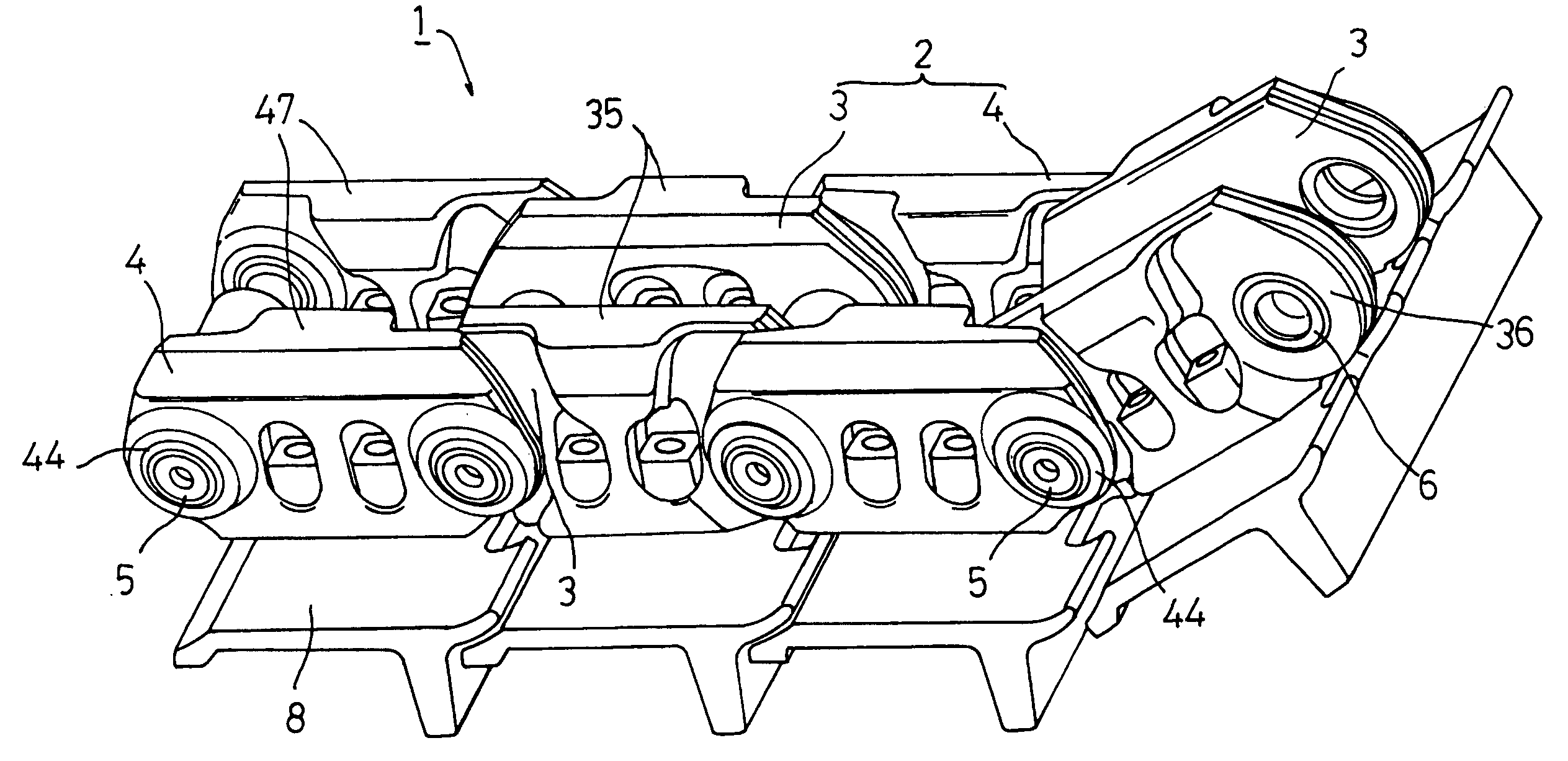
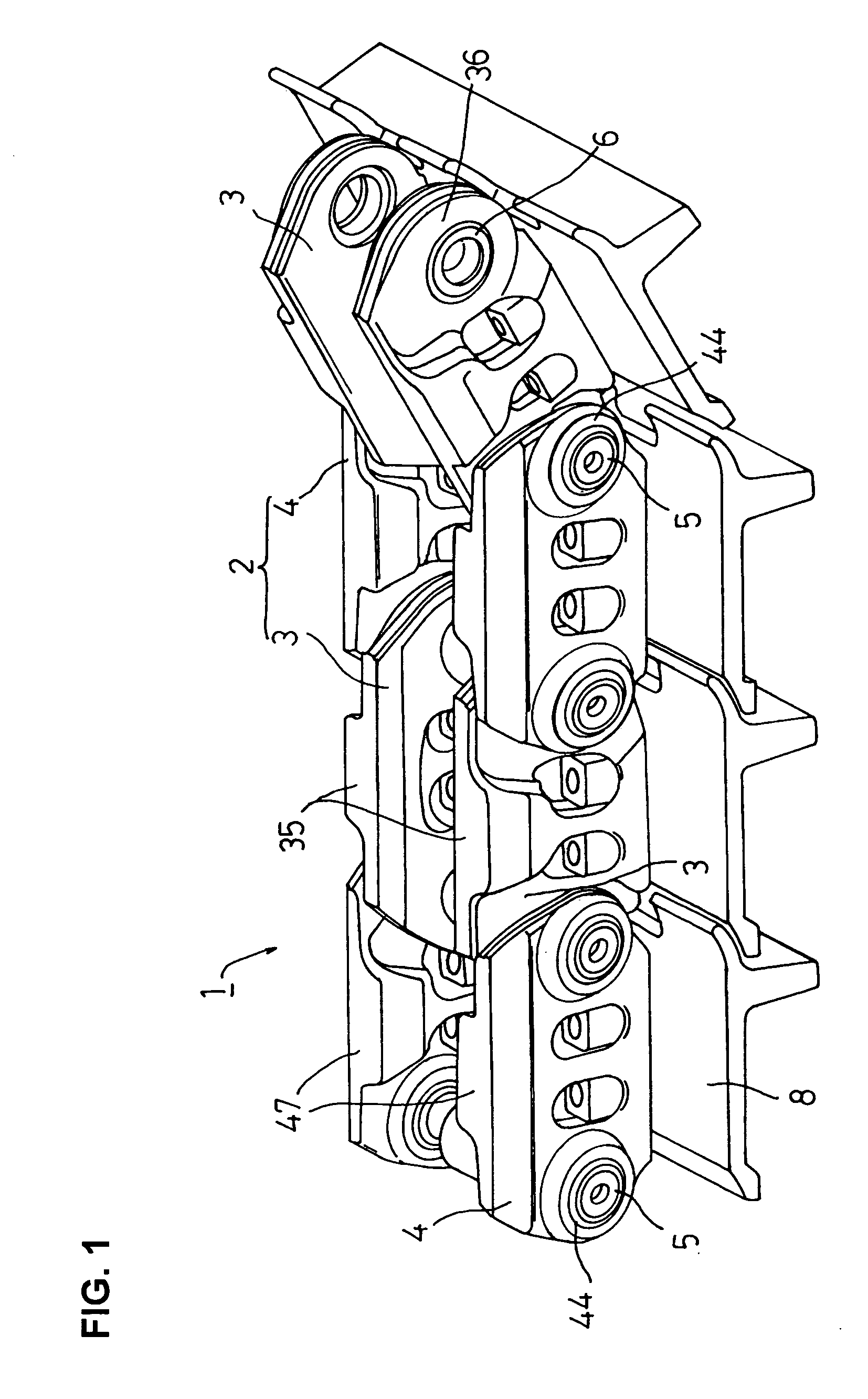
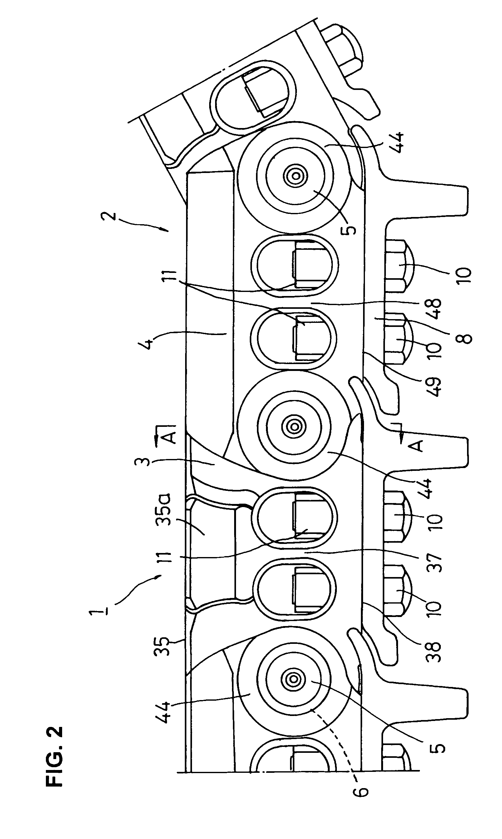
[0028]FIG. 1 is a partial perspective illustration of a track according to an embodiment of the present invention. FIG. 2 is a partial front view of the track. FIG. 3 is a top plan view showing, in cross section, a part of FIG. 2. FIG. 4 is an enlarged cross sectional view taken on the line A-A of FIG. 2. FIG. 5 is a perspective illustration of an internal link of the track. FIG. 6 is a perspective illustration of an external link of the track.
[0029] A track 1 with a rotatable bushing of the present embodiment is usually incorporated into an undercarriage (not shown) of a track-type construction machine (work machine) such as a hydraulic excavator, a bulldozer et cetera. As partially shown in FIG. 1, the track 1 with the rotatable bushing (hereinafter called the “track 1”)...
PUM
| Property | Measurement | Unit |
|---|---|---|
| Thickness | aaaaa | aaaaa |
| Area | aaaaa | aaaaa |
| Surface area | aaaaa | aaaaa |
Abstract
Description
Claims
Application Information