Motor coupling device

a technology of motor coupling and coupling shaft, which is applied in the direction of engine-driven generator propulsion, transportation and packaging, hoisting equipment, etc., can solve the problems of generating noise or excessive noise or vibration, generating noise or excessive noise, etc., and reducing impact or excessive noise and vibration , the effect of smooth transmission and simple configuration

Active Publication Date: 2016-12-29
HYUNDAI MOTOR CO LTD
View PDF18 Cites 3 Cited by
  • Summary
  • Abstract
  • Description
  • Claims
  • Application Information

AI Technical Summary

Benefits of technology

[0030]Accordingly, embodiments of the present disclosure may reduce impact or excessive noise and vibration due to motor bi-direction (+)(−) backlash and may smoothly transmit power between the motor and the drivetrain by compensating for the bi-direction (+)(−) backlash of a motor through first and second backlash compensation units having a simple configuration.

Problems solved by technology

However, in conventional systems, when rotation angular acceleration of the driver motor is changed (e.g., upon regenerative braking) while a driving torque of the drive motor is transferred to the drivetrain through a coupling, a nonlinear behavior may be generated due to an inertia difference between the drive motor and the drivetrain.
When a direction of the driving torque is changed, impact or excessive noise or vibration may be generated.
However, such systems rely on backlash through a proper mechanical design of an element to fundamentally connect the drive motor to the drivetrain such as through a coupling.

Method used


Image

  • Motor coupling device
  • Motor coupling device
  • Motor coupling device

Examples


Embodiment Construction

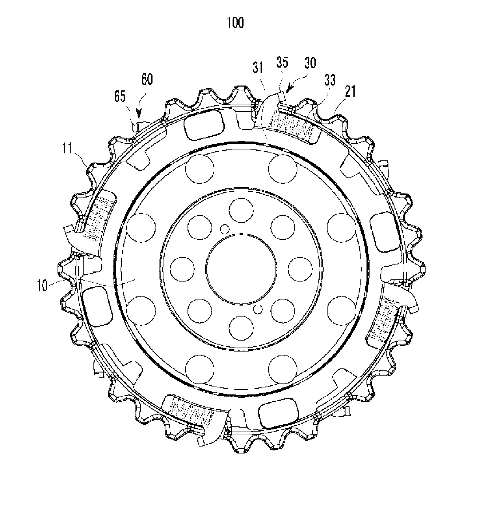
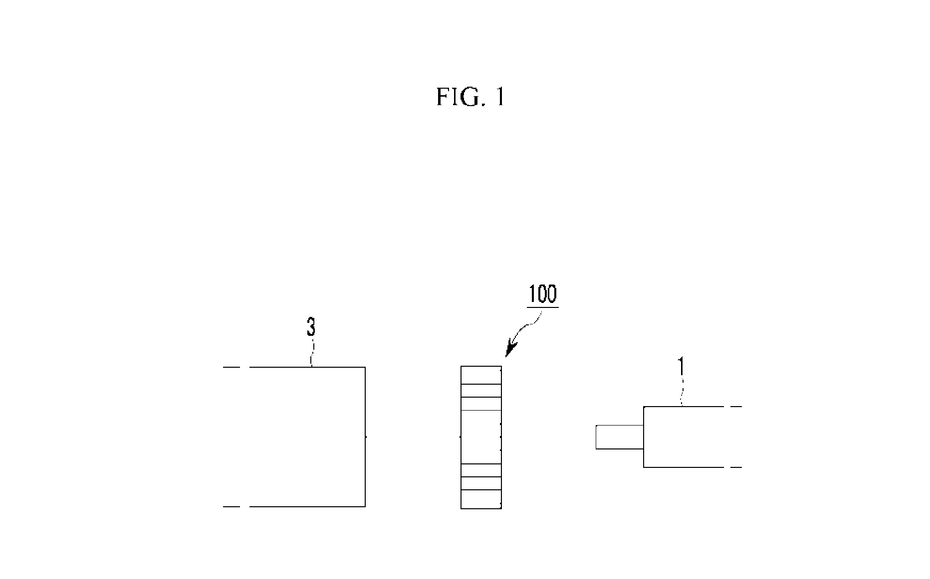
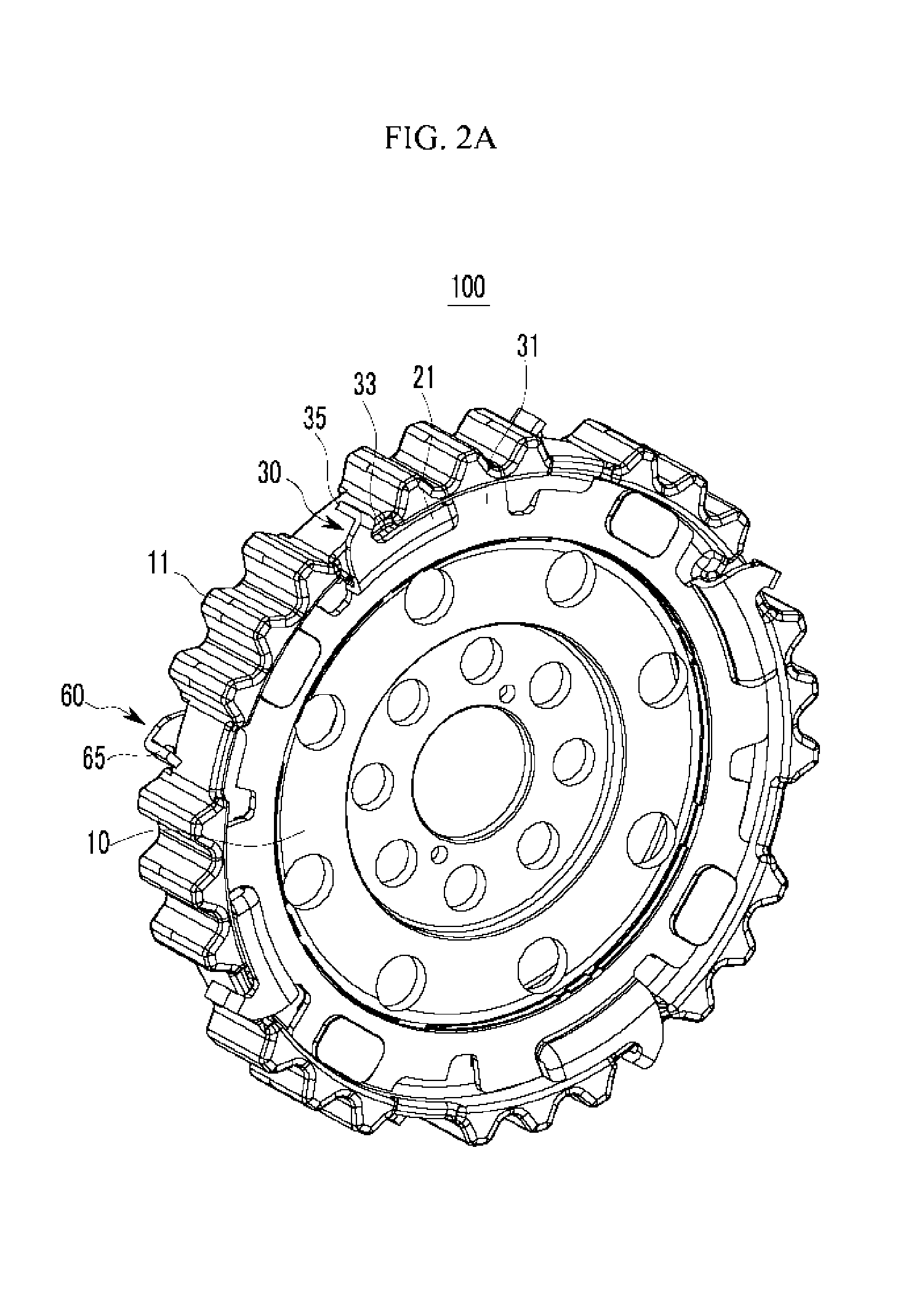
[0040]The present disclosure will be described more fully hereinafter with reference to the accompanying drawings, in which embodiments of the disclosure are shown. As those skilled in the art would realize, the described embodiments may be modified in various different ways, all without departing from the spirit or scope of the present disclosure.

[0041]Parts irrelevant to the description are omitted to clearly illustrate the present disclosure, and like reference numbers designate like constituent elements through the specification. Further, the size and thickness of each configuration shown in the drawings are arbitrarily illustrated for better understanding and ease of description, so the present disclosure is not limited to shown drawings, and thicknesses are exaggerated for clarity of a plurality of parts and regions.

[0042]In the following detailed description, the terms “first” and “second” will be used to discriminate one component from another component, but the components m...


PUM


Abstract

A motor coupling device for connecting a drivetrain of a hybrid vehicle to a motor and transferring a driving torque of the motor to the drivetrain, the motor coupling device comprising: a coupling plate connected to a rotation shaft of the motor and engaging with a connecting plate of the drivetrain; and a first backlash compensation unit installed at one surface of the coupling plate, interfering with the connecting plate, and compensating for backlash when a motor reverse torque is generated.

Description

CROSS-REFERENCE TO RELATED APPLICATION[0001]This application claims priority to and the benefit of Korean Patent Application No. 10-2014-0172126 filed in the Korean Intellectual Property Office on Dec. 3, 2014, the entire contents of which are incorporated herein by reference.BACKGROUND OF THE DISCLOSURE[0002](a) Technical Field[0003]The present disclosure relates generally to an environmentally friendly vehicle, and more particularly, to a motor coupling device which connects a drivetrain of a hybrid vehicle to a motor, and transfers a driving torque of the motor to the drivetrain.[0004](b) Description of the Related Art[0005]In general, environmentally-friendly vehicles such as a hybrid vehicle or an electric vehicle may generate a driving torque by an electric motor (hereinafter referred to as “drive motor”) for obtaining a rotating force based on electrical energy. For example, a hybrid vehicle runs in an electric vehicle (EV) mode that is a pure electric mode using only power o...

Claims


Application Information

Patent Timeline
Patent Type & Authority Applications(United States)
IPC IPC(8): F16H57/12F16H55/18B60L50/16
CPCF16H55/18F16H57/12F16H55/14B60K17/02Y10T74/19902B60K6/00B60K6/26H02K7/116Y02T10/7072F16H2057/126
Inventor RYU, SANGMOKIM, MYUNGGYUYANG, HONG SEOKLEE, JUNGWOO
Owner HYUNDAI MOTOR CO LTD
Why Eureka
Try Eureka