

Use of cerium salts to inhibit manganese deposition in water systems
- Summary
- Abstract
- Description
- Claims
- Application Information
AI Technical Summary
Benefits of technology
Problems solved by technology
Method used
Image

Examples
examples
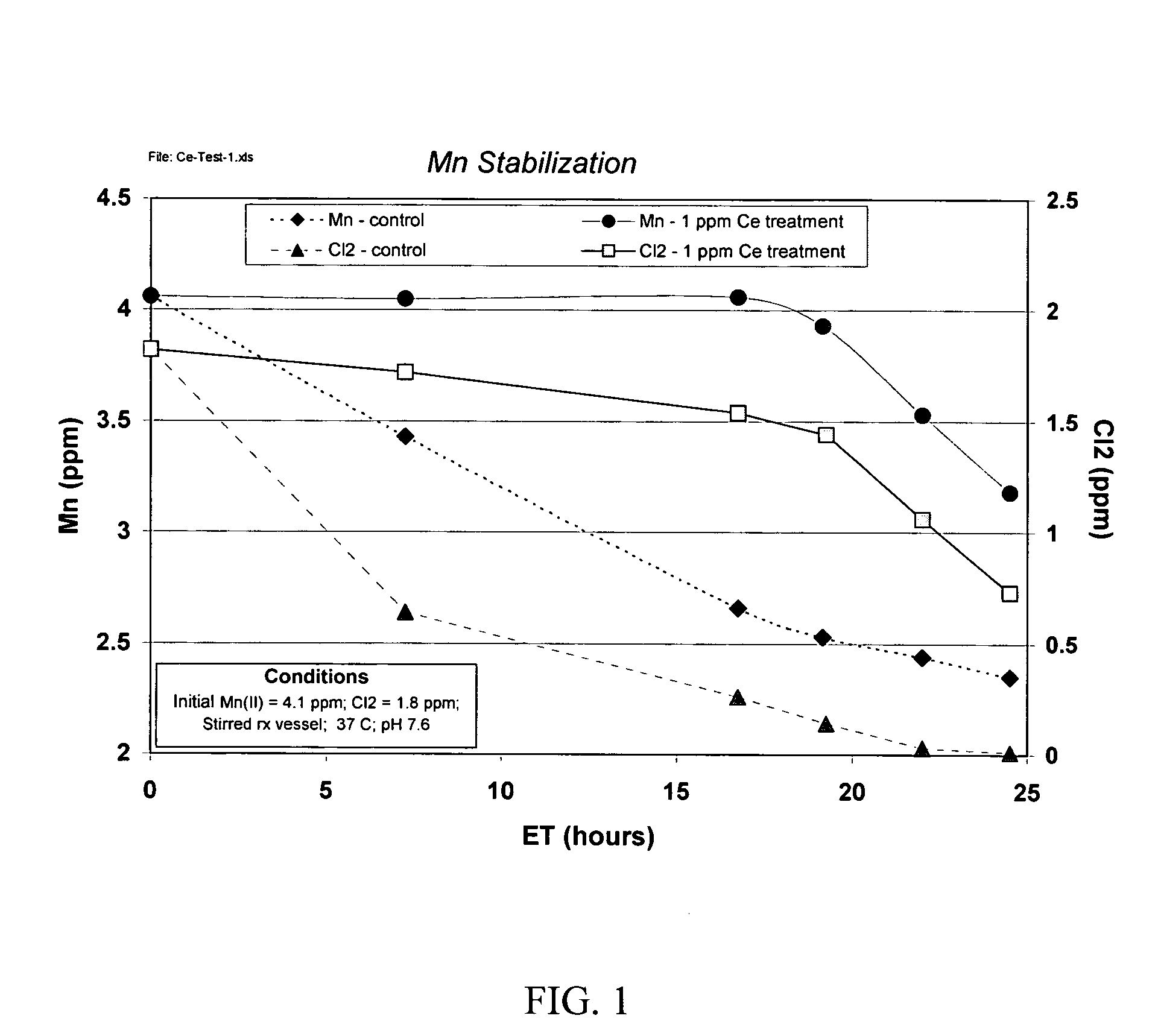
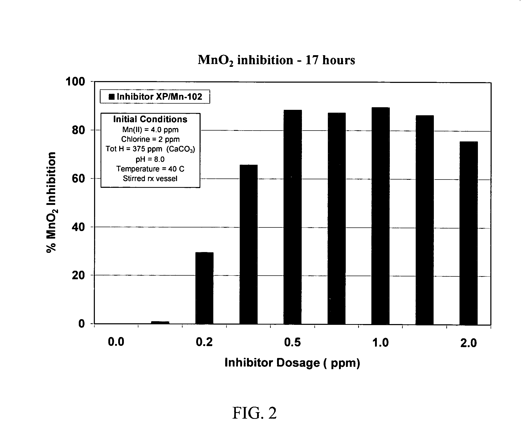
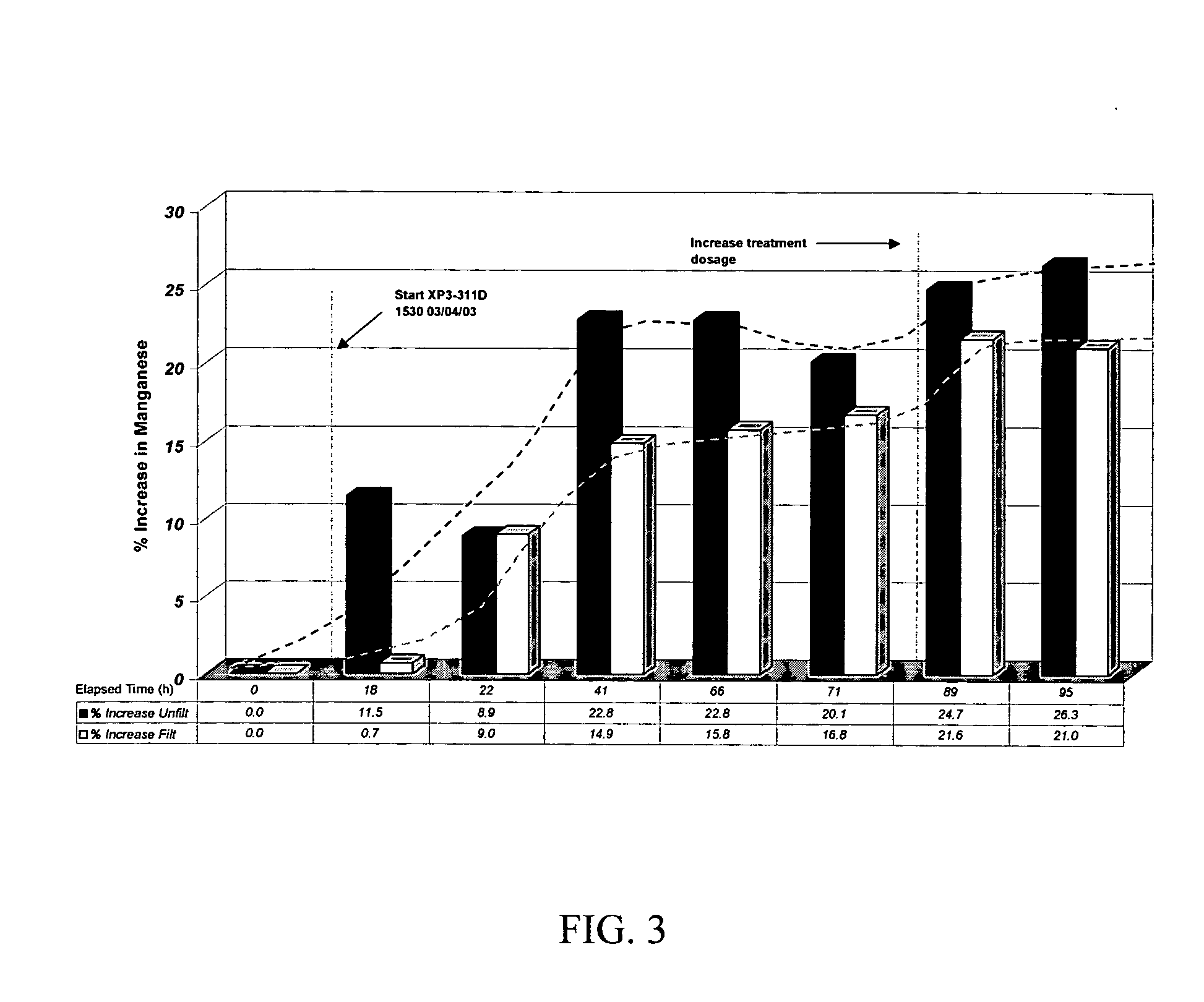
The performance of a treatment according to the present invention to control manganese deposition in an aqueous system can be evaluated by exposing Mn(II)-containing solutions to conditions that cause MnO2 to form, and then determining the amount of dissolved manganese remaining after insoluble MnO2 has been removed from the solution, by filtration through a sub-micron filter. Manganese in the filtrate is either dissolved or in a finely divided, easily dispersed state that does not precipitate as readily as the coarser material. Higher levels of manganese in the filtrate correspond to improved inhibition of manganese deposition.
Cerium Inhibition of Manganese Oxidation by Chlorine
To assess the ability of cerium to inhibit manganese oxidation by chlorine, an aqueous solution containing soluble divalent manganese and sodium hypochlorite was allowed to incubate for periods up to 24 hours. The aqueous solution was then passed through a 0.2 micron filter and manganese in the filtrate ...
PUM
| Property | Measurement | Unit |
|---|---|---|
| Fraction | aaaaa | aaaaa |
| Composition | aaaaa | aaaaa |
| Weight ratio | aaaaa | aaaaa |
Abstract
Description
Claims
Application Information