Clamping apparatus and methods for manufacturing

a manufacturing method and clamping technology, applied in the field of clamping, can solve the problems of not being able to engage the clamping in most or all of the surrounding areas of the tool, and not being able to secure the workpiece in position near the point where the manufacturing tool engages the workpiece,

Inactive Publication Date: 2005-05-05
THE BOEING CO
View PDF20 Cites 56 Cited by
  • Summary
  • Abstract
  • Description
  • Claims
  • Application Information

AI Technical Summary

Benefits of technology

[0005] The present invention is directed to an apparatus and methods for clamping around a manufacturing tool engaging a work piece. In one embodiment, a clamp includes a moveable support arranged to at least partially surround a circumference defining a work area. A friction reducing element is attached to the support to a

Problems solved by technology

In manufacturing operations where a tool engages the work piece with substantial force, clamping near where the manufacturing tool engages the work piece may not

Method used


Image

  • Clamping apparatus and methods for manufacturing
  • Clamping apparatus and methods for manufacturing
  • Clamping apparatus and methods for manufacturing

Examples


Embodiment Construction

[0030] The present invention relates to apparatus and methods for a clamping device. Many specific details of certain embodiments of the invention are set forth in the following description and in FIGS. 1-10 to provide a thorough understanding of such embodiments. One skilled in the art, however, will understand that the present invention may have additional embodiments, or that the present invention may be practiced without several of the details described in the following description.

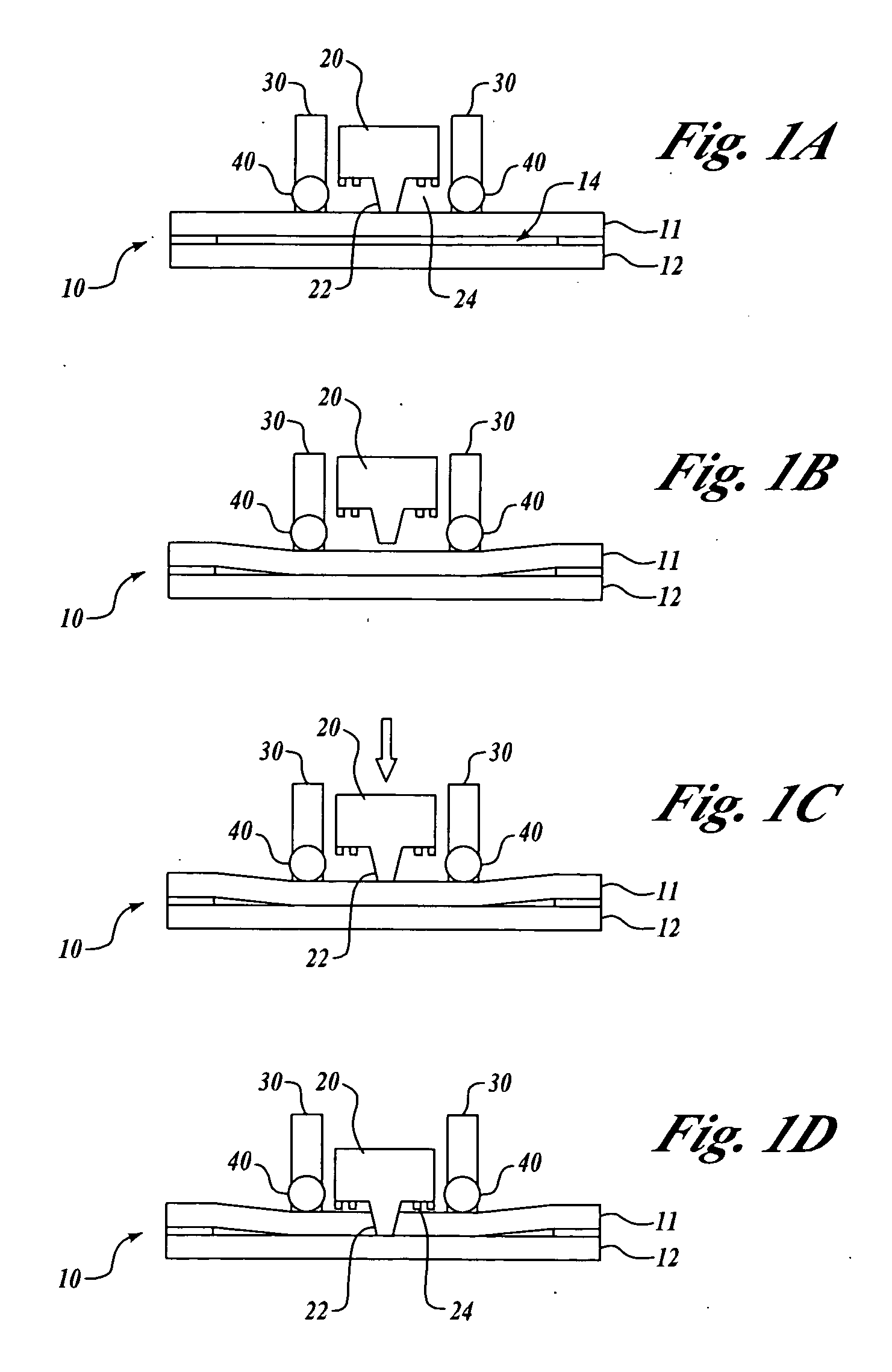
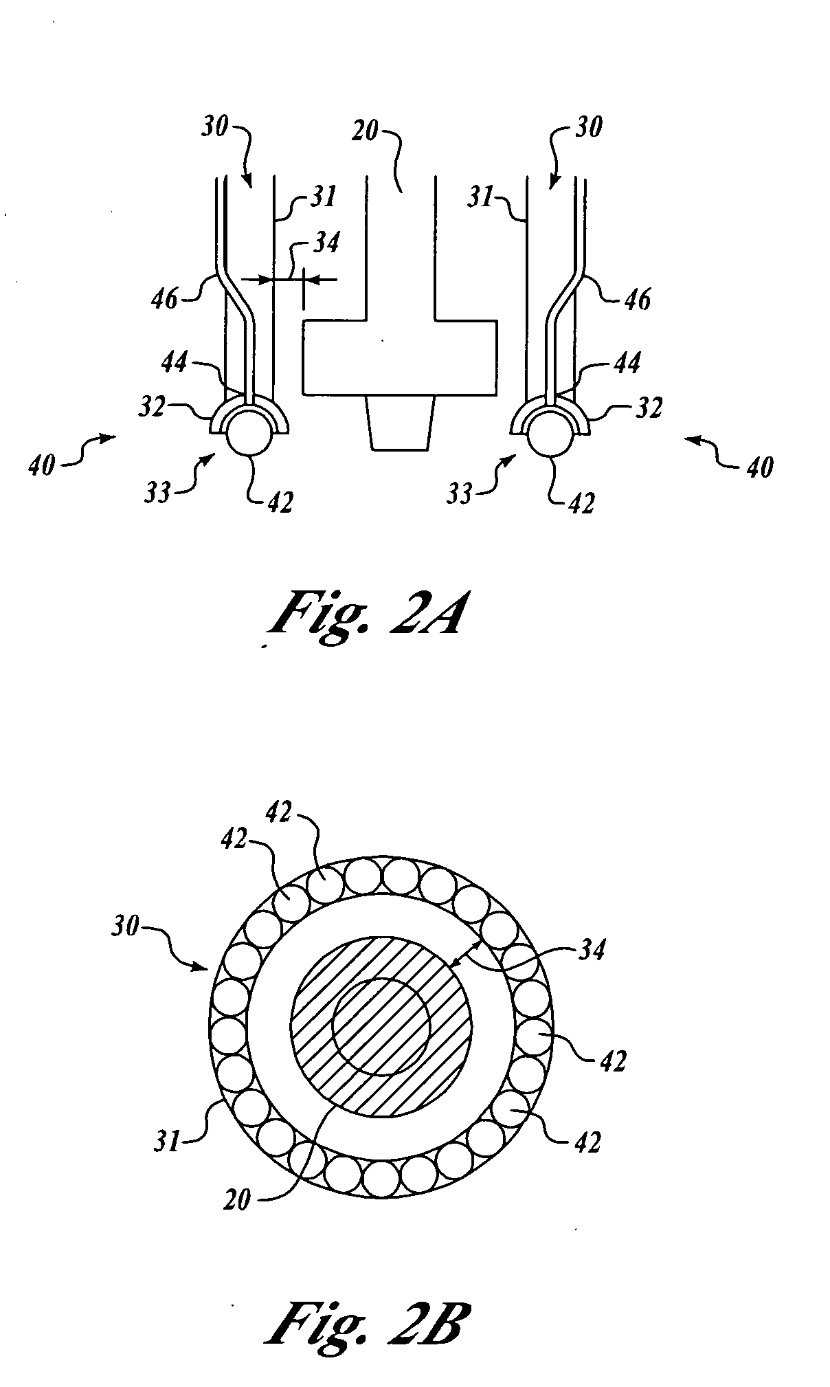
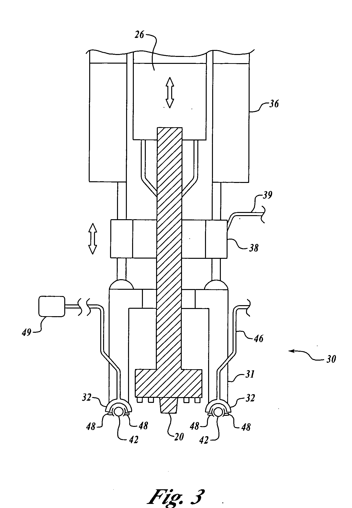
[0031]FIGS. 1A through 1D are side view cross sections of an exemplary clamp 30 of the present invention used for a lap weld. In this embodiment, the clamp 30 co-annularly surrounds a friction stir welding tool 20 so that clamping force can be applied to a work piece 10 when the friction stir welding tool 20 is engaged with the work piece 10. It will be appreciated that the clamp 30 of the present invention may be utilized with any manufacturing tool such as routers, cutters, and other welding device...


PUM

PropertyMeasurementUnit
Forceaaaaaaaaaa
Pressureaaaaaaaaaa
Diameteraaaaaaaaaa

Abstract

The present invention is directed to apparatus and methods for clamping around a manufacturing tool engaging a work piece. In one embodiment, a clamp includes a moveable support arranged to at least partially surround a circumference defining a work area. A friction reducing element is attached to the support to apply pressure to the surface when the clamp is engaged with the work piece, and to allow the clamp to be moved with the manufacturing tool. In accordance with other aspects of the invention, the clamp co-annularly or partially surrounds the manufacturing tool. In another embodiment, the manufacturing tool is a friction stir welding tool.

Description

FIELD OF THE INVENTION [0001] This invention relates generally to clamping and, more specifically, to clamping during manufacturing operations. BACKGROUND OF THE INVENTION [0002] During manufacturing work such as machining, routing, cutting, and welding, the work pieces are often held by clamps when a manufacturing tool engages the work piece. Typically such clamps are placed independently from the manufacturing tool. Such clamps include bar clamps, c-clamps, vises, and similar clamping tools. In manufacturing operations where a tool engages the work piece with substantial force, clamping near where the manufacturing tool engages the work piece may not be sufficient to hold the work piece in position. There may be a distance between the manufacturing tool and the applied clamp or clamps. Further, clamping may not be engaged in most or all areas surrounding the tool as the tool engages the work piece. [0003] In friction stir welding, a process that plastically bonds metals, plunging ...

Claims


Application Information

Patent Timeline
IPC IPC(8): B23K20/12B23Q3/06B25B5/00
CPCB23K20/126B25B5/00B23Q3/069B23Q3/002
Inventor BAUMANN, JOHN A.LEDERICH, RICHARD J.
Owner THE BOEING CO
Why Eureka
Try Eureka