Method for driving electro-optical device, electro-optical device and electronic equipment

a technology of electrooptical devices and electronic equipment, applied in static indicating devices, instruments, solid-state devices, etc., can solve the problems of insufficient supply of data current in the low grayscale region, difficult to complete the writing (supply) of program data current, and affecting the quality of display quality

Inactive Publication Date: 2005-05-19
SEIKO EPSON CORP
View PDF8 Cites 7 Cited by
  • Summary
  • Abstract
  • Description
  • Claims
  • Application Information

AI Technical Summary

Benefits of technology

[0020] Electro equipment of a third exemplary embodiment can include the above-mentioned electro-optical device. Accordingly, the display that is excellent in display quality and able to solve the insufficient supply of the data current and current fluctuation can be achieved.

Problems solved by technology

However, a grayscale shift can occur due to the change of supply current to the organic EL element caused by fluctuation in the operating point of a driving transistor (TFT) and an incomplete writing (insufficient supply) of a data current in a low grayscale region.
In sum, the insufficient supply of the data current in the low grayscale region is caused by wiring resistance and wiring capacitance in a data line supplying a program data current to a pixel circuit.
Accordingly, the smaller of the program data current is, namely more in the low grayscale region, the more difficult to complete the writing (supply) of the program data current to a capacitance element in the pixel circuit within the predetermined time.
Thus, this insufficient supply results in the luminance shift.

Method used


Image

  • Method for driving electro-optical device, electro-optical device and electronic equipment
  • Method for driving electro-optical device, electro-optical device and electronic equipment
  • Method for driving electro-optical device, electro-optical device and electronic equipment

Examples


Embodiment Construction

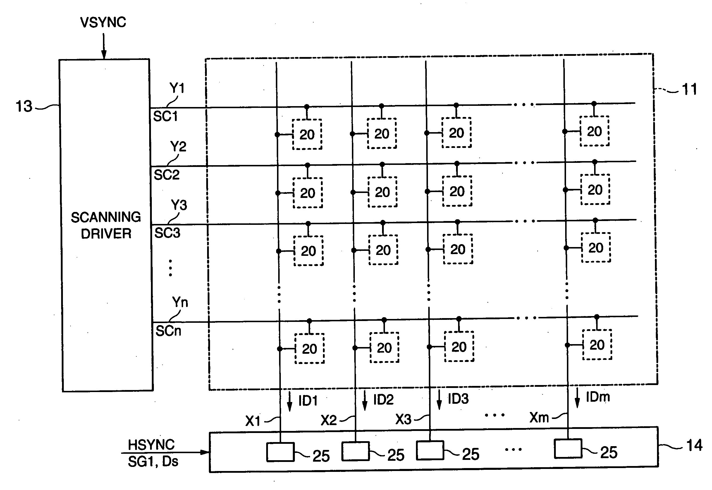
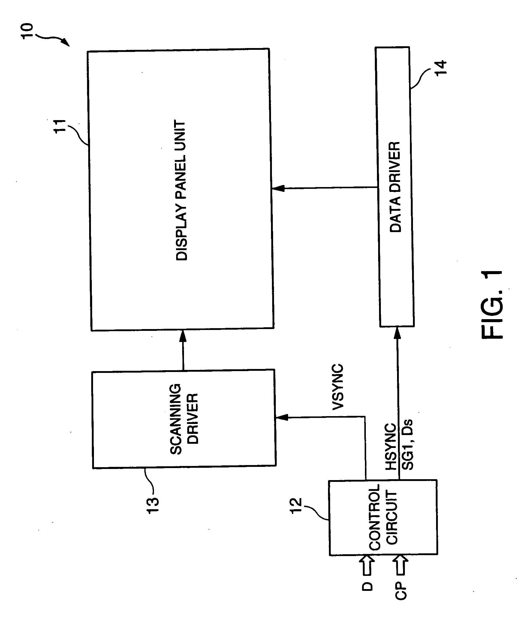
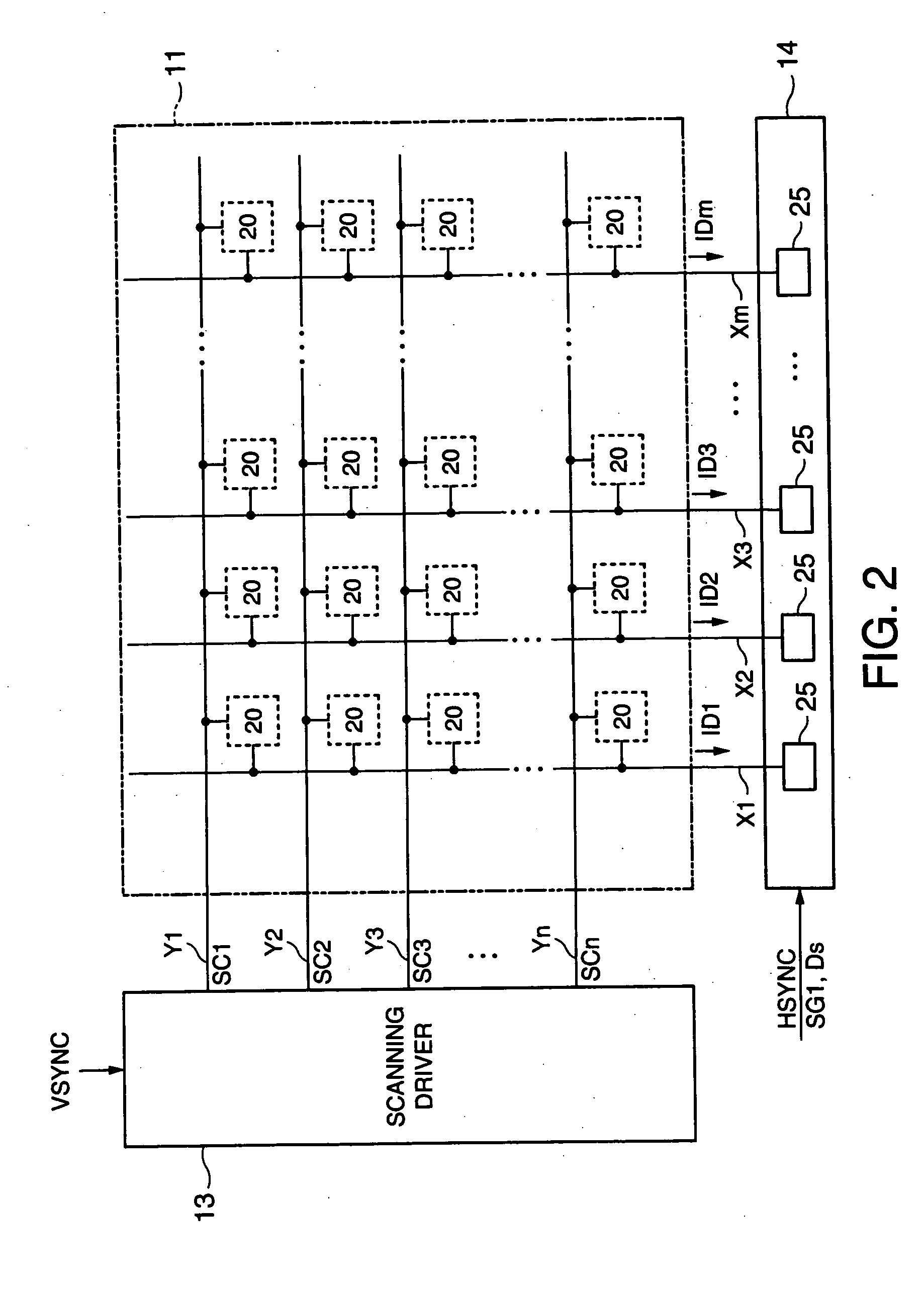
[0029] A first exemplary embodiment of the invention will be explained below with reference to FIGS. 1 through 5. FIG. 1 is an exemplary block circuit diagram illustrating electrical construction of an organic electro luminescence (Electro Luminescence; hereinafter referred as EL) display device that is an example of an electro-optical device embodying the invention. In FIG. 1, an organic EL display device 10 can include a display panel unit 11, a control circuit 12, a scanning driver 13 and a data driver 14.

[0030] The control circuit 12, the scanning driver 13 and the data driver 14 of the organic EL display device 10 may be constructed with discrete electronic components. For example, the control circuit 12, the scanning driver 13 and the data driver 14 may be constructed with a one-chip semiconductor integrated circuit device. In addition, the control circuit 12, the scanning driver 13 and the data driver 14 may be constructed as the electronic component in which all of them or ...


PUM


Abstract

Aspects of the invention can provide a method for driving an electro-optical device, an electro-optical device and electronic equipment that can solve the insufficient supply of the data current and current fluctuation. In the driving method, a data current can be applied to a plurality of pixels provided to a display panel unit with same value through the data line regardless of grayscale data. Upon supply of the data current, in the pixel, a transistor selected in reproduction can be turned on such that a drive current corresponding to the data current output from a driving transistor is supplied to an organic EL element, thereby emitting light. A light-off signal can be supplied to the pixel at predetermined timing such that the organic EL element emits light only in the light-emitting period computed based on the grayscale data. The pixel to which a constant data current can be supplied emits light at a luminance corresponding to the grayscale data by changing the light-emitting period corresponding to the grayscale data.

Description

BACKGROUND OF THE INVENTION [0001] 1. Field of Invention [0002] Aspects of the invention can relate to a method for driving electro-optical device, an electro-optical device and electronic equipment. [0003] 2. Description of Related Art [0004] Related art organic electro luminescence display devices (organic EL display device) can be referred to as electro-optical devices, and can include an electro-optical element made of an organic EL material. Related art electro-optical device can also have excellent characteristics of self-luminous, high luminance, high-angle-of-field, low profile, quick response, and low power consumption. Further, such devices can be made to be smaller and lighter with a peripheral driving circuit using a polysilicon TFT (Thin Film Transistor). [0005] Incidentally, this kind of organic EL display device has a luminance variation between pixels. Thus, various kind of driving methods including a current program method are proposed. See, for example, U.S. Pat. N...

Claims


Application Information

Patent Timeline
Patent Type & Authority Applications(United States)
IPC IPC(8): H01L51/50G09G3/20G09G3/30G09G3/32
CPCG09G3/2022G09G3/325G09G3/3258G09G3/3275G09G2330/021G09G2300/0861G09G2310/0248G09G2310/061G09G2320/0233G09G2300/0842G09G3/30
Inventor KIMURA, MUTSUMIHARA, HIROYUKI
Owner SEIKO EPSON CORP
Why Eureka
Try Eureka