System and method for improved auto-boating

Active Publication Date: 2005-05-26
TEXAS INSTR INC
View PDF2 Cites 5 Cited by
  • Summary
  • Abstract
  • Description
  • Claims
  • Application Information

AI Technical Summary

Benefits of technology

[0005] Some embodiments of the invention provide numerous technical advantages. Other embodiments may realize some, none, or all of these advantages. For example, protrusions at the four corners of a tape substrate create small extensions at the edges of the tape substrate, which substantially eliminates the possibility of contact between the edges of the tape substrate and the clip windows. Hence, the tape substrate slides in place when the clip is pushed downward onto the tape substrate and any bowing / warping along the edges of the tape substrate is eliminated. These protrusions may easily be fabricated onto the edges of the tape substrate without having to change the length of the tape from which tape substrates are formed.

Problems solved by technology

Because of the ever decreasing thickness of some substrates, such as tape substrates, the die attach process becomes even more important because of the challenges present when attaching die to these types of substrates.
However, since the clip holds down only a very small strip of the substrate along its edges, the possibility of the substrate edges getting jammed with the clip windows at the ends of the clip is high because of the coiling effect when placing a tape substrate on a boat.
This leads to substrate bowing and warping along its edges, which means that the integrated circuit dies formed along the edges of the tape substrate may have to be scrapped, which hurts yield.

Method used


Image

  • System and method for improved auto-boating
  • System and method for improved auto-boating

Examples


Embodiment Construction

[0011] Example embodiments of the present invention and their advantages are best understood by referring now to FIGS. 1 through 3B of the drawings, in which like numerals refer to like parts.

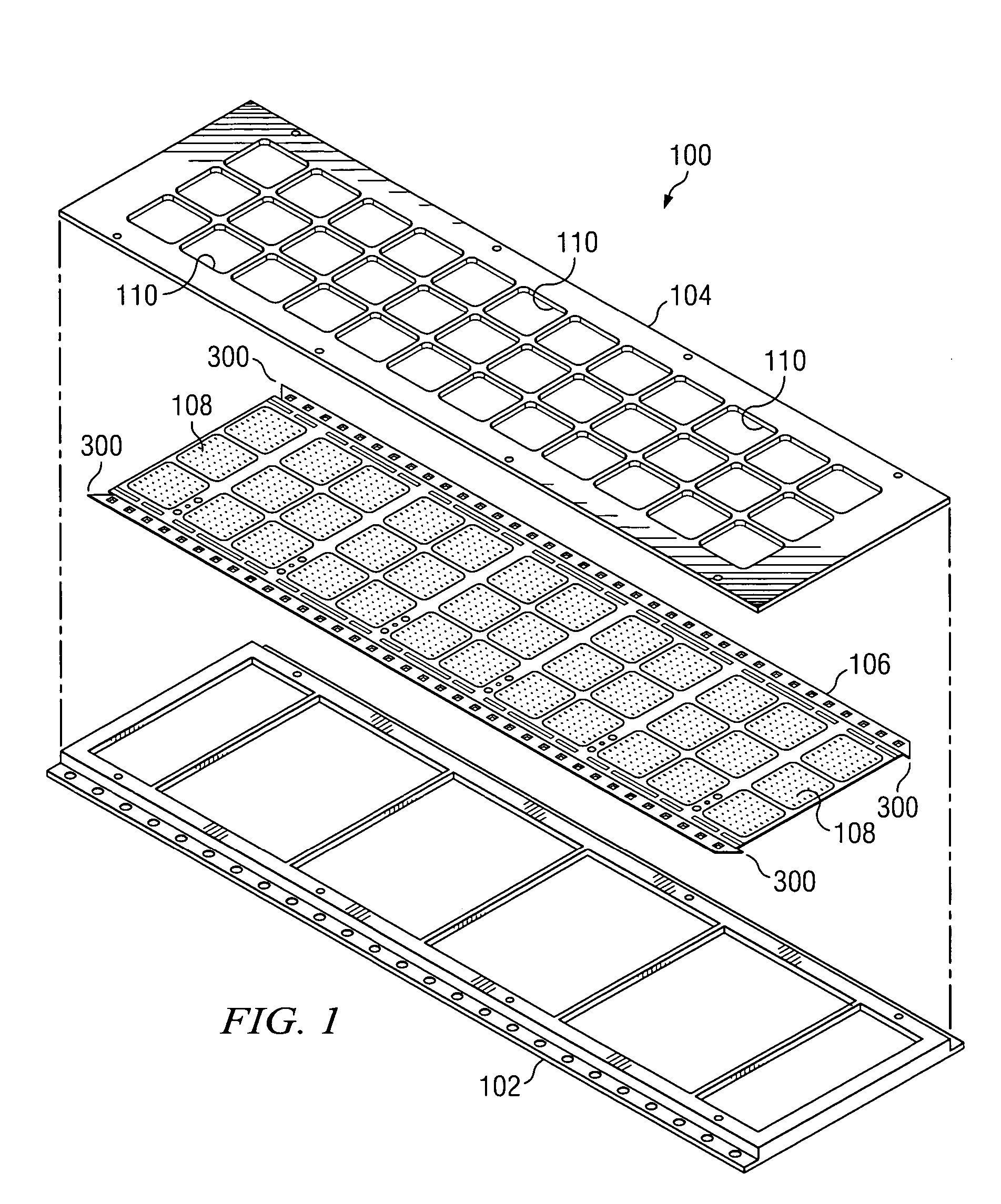
[0012]FIG. 1 is an exploded, perspective view of a system 100 utilized in an auto-boating process according to one embodiment of the present invention. The auto-boating process is well known in the integrated circuit fabrication industry. Hence, all details of such a process may not be fully described herein. Generally, system 100 is utilized in the fabrication of integrated circuits, such as ball grid arrays (“BGAs”). In the illustrated embodiment, system 100 includes a boat 102, a boat clip 104, and a tape substrate 106 disposed therebetween. Tape substrate 106 has a plurality of die attach regions 108 in which integrated circuit die are coupled thereto in order to fabricate individual integrated circuits.

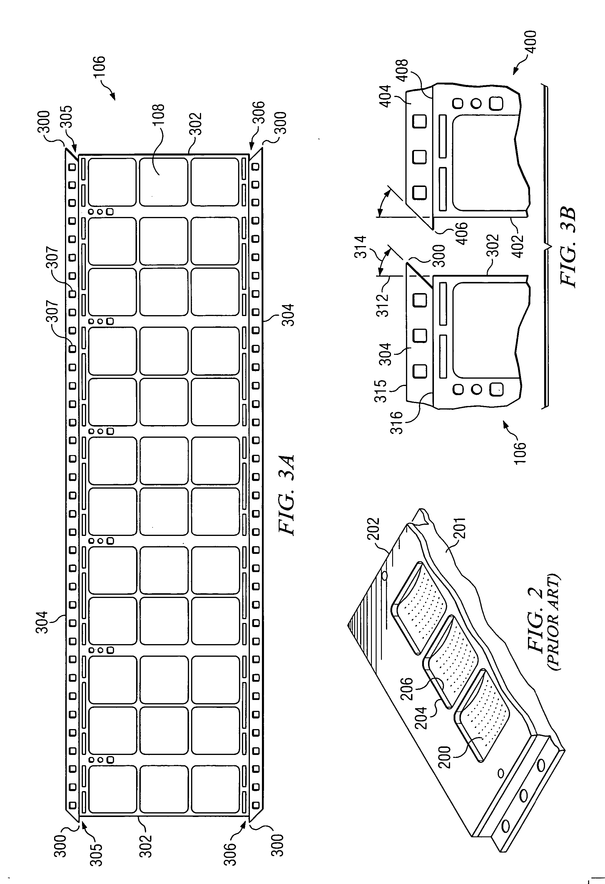
[0013] Generally, boat 102 is used as a carrier for tape substrate 106 during the fabr...


PUM


Abstract

According to one embodiment of the invention, a system used in auto-boating includes a tape substrate supported by a boat. The tape substrate includes a pair of lateral edges parallel to one another and each having respective first and second ends, and a pair of longitudinal guide strips parallel to one another. One of the longitudinal guide strips extends between the respective first ends of the pair of lateral edges and the other longitudinal guide strip extends between the respective second ends of the pair of lateral edges. The tape substrate also includes a plurality of die attach regions disposed within the area defined by the pair of lateral edges and the pair of longitudinal guide strips. The system further includes a boat clip coupled to the boat such that the tape substrate is sandwiched between the boat and the boat clip. Each longitudinal guide strip includes a pair of tabs disposed at opposite ends thereof such that each tab extends beyond a respective one of the lateral edges.

Description

TECHNICAL FIELD OF THE INVENTION [0001] This invention relates generally to the field of integrated circuit packaging and, more specifically, to a system and method for improved auto-boating. BACKGROUND OF THE INVENTION [0002] Because of the sheer volume of integrated circuits in the marketplace, packaging of integrated circuits in a manner that is cost-effective with high yield is important for semiconductor manufacturers in order that they can be competitive in the marketplace. One important process in the fabrication of integrated circuits is the die attach process. Because of the ever decreasing thickness of some substrates, such as tape substrates, the die attach process becomes even more important because of the challenges present when attaching die to these types of substrates. [0003] The auto-boating process, which sandwiches a tape substrate between a boat and a clip, greatly enhances the die attach process for tape substrates. However, since the clip holds down only a very...

Claims


Application Information

Patent Timeline
IPC IPC(8): H01L21/68H01L23/538
CPCH01L21/6835H01L23/5387H01L2924/0002Y10T156/1062Y10T156/10H01L2924/00
Inventor CRUZ, MARK GERALD M.CAYABYAB, JERRY G.
Owner TEXAS INSTR INC
Why Eureka
Try Eureka