Thus, they are expensive to manufacture, especially the moving portion or valve body.
Prior efforts to reduce
distortion under load by strengthening such valve bodies have generally resulted in higher cost and / or heavier designs which exacerbate sealing problems and / or increase the stress of
impact loading on components of the valve
assembly.
Commercially important design improvements necessarily reflect the fact that certain
mud pump valve body and seat dimensions are effectively limited by industry practices and American
Petroleum Institute (API) Standards.
Given these constraints, attempts to reduce fatigue failures and / or improve valve performance have led to "improved" designs which are more expensive to manufacture and have different failure
modes than earlier versions.
But such valve bodies have several disadvantages in manufacture and use.
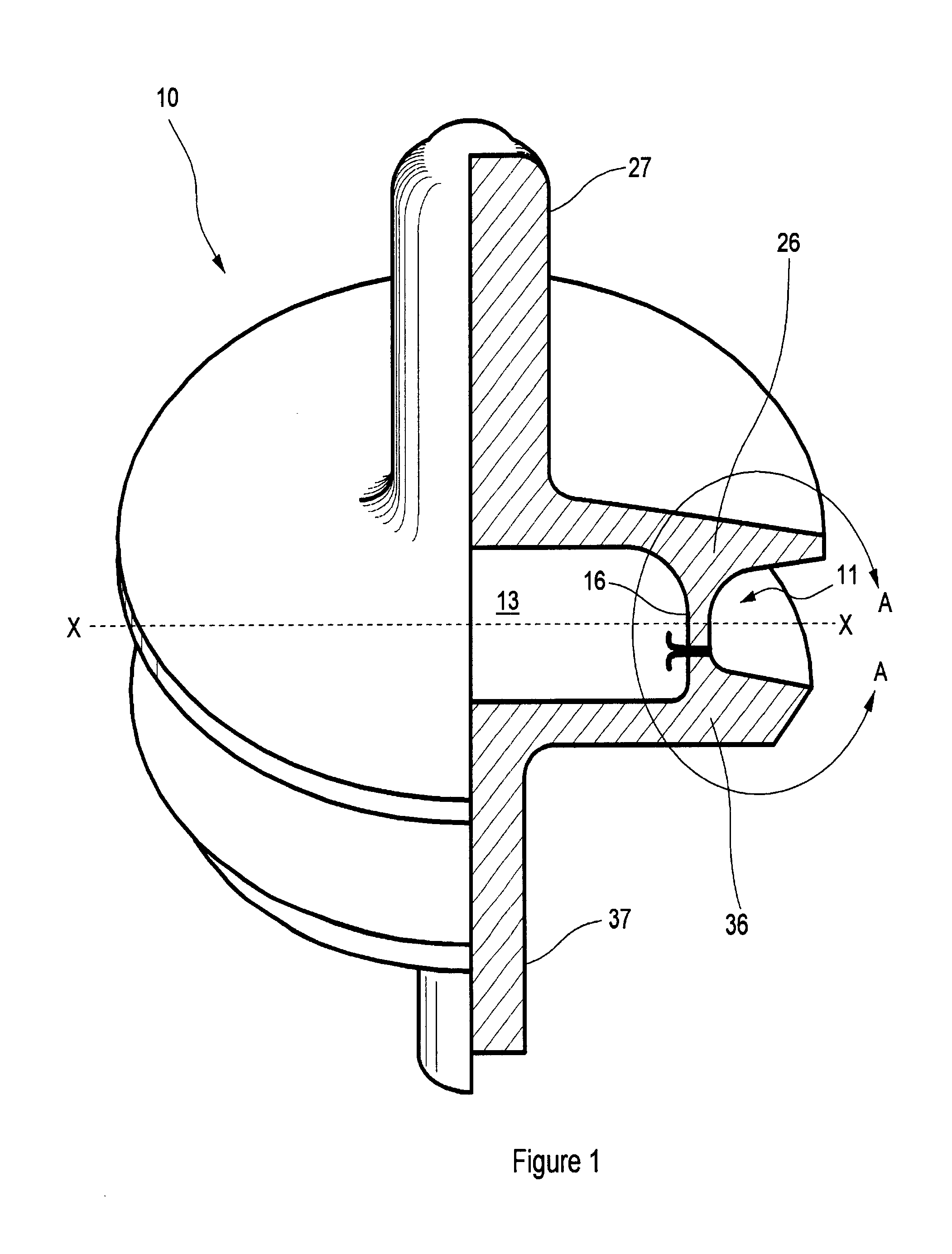
First, rough valve body forgings in the Channel-
Beam shape require substantial
material removal in finish machining of the integral seal retention groove.
Second, an elastomeric seal snapped into the seal retention groove may not fully seat around the entire valve body, causing an out-of-round condition that can result in early valve failure.
Avoidance of thin portions, on the other hand, imposes weight penalties that result in greater
impact loading.
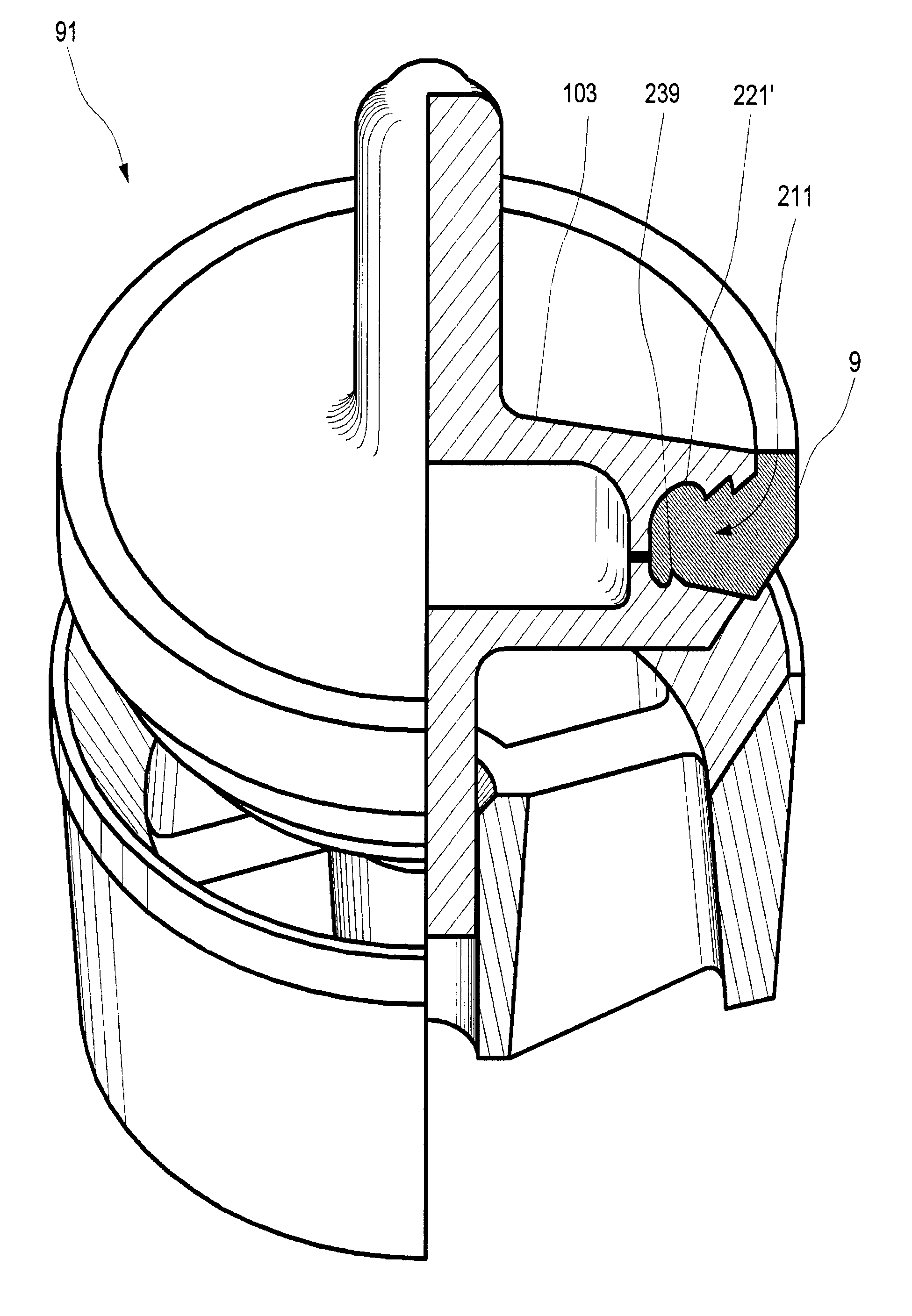
Notwithstanding their relatively high cost, however, valve bodies having an integral seal retention groove (i.e., a seal retention groove having no removable seal retention plate or other analogous removable structural member) such as the one-piece Channel-Beam design have gained limited industry acceptance.
This type of
distortion is particularly a problem on valve bodies that mate with web seats.
Cyclical
high pressure applied to such a valve body when it is sealed against a web seat tends to repeatedly force portions of the valve body into the spaces between the seat webs.
On multi-piece valve bodies (i.e., valve bodies having a removable seal retention plate), such
cyclic loading induces fatigue that can lead to further
distortion and / or failure of the valve
flange.
Countering such distortion by simply making the
flange thicker increases total valve
body weight, which in turn increases wear due to higher
impact loading of both the valve body and seat.
Valve bodies of Channel-Beam design minimize such distortion in part through their inherent rigidity and strength, but they weigh even more than comparable multi-piece valve bodies and so suffer the
disadvantage of higher impact loads in use.
Another important
disadvantage of the Channel-Beam design, as noted above, relates to seating of the seal insert.
Practical advantages of such a seal insert include extended valve life and improved valve performance, but proper fitting and sealing of the elastomeric ring on a valve body is often difficult in the field.
For example, the snap-on insert may not exactly fit the Channel in a Channel-Beam valve body.
The installed seal may then be out-of-round, leading to premature seal failure and subsequent failure of the valve body and web seat.
When such a seal fails, leaking high-pressure fluid will jet through the initial leak path.
If the valve remains in service, the leaking, jetting high-pressure fluid will literally wash away the
hardened steel of the valve body and / or seat.
Multiple and near-simultaneous failures of a single seal ring may give a valve body
flange the appearance of a wrinkled cupcake paper.
Such bonding of the cured seal to the groove wall is expensive, and it also tends to reduce the service life of the seal due to
internal stress induced as the curing
elastomer tends to shrink away from the walls to which it is bound.
Additionally, field replacement of such seals is not practical.
Another
disadvantage of Channel-Beam valve bodies is their relatively high manufacturing cost.
They are expensive to manufacture because the forgings from which they are machined are not near-net-shape.
But they also raise valve fabrication costs and impose use restrictions.
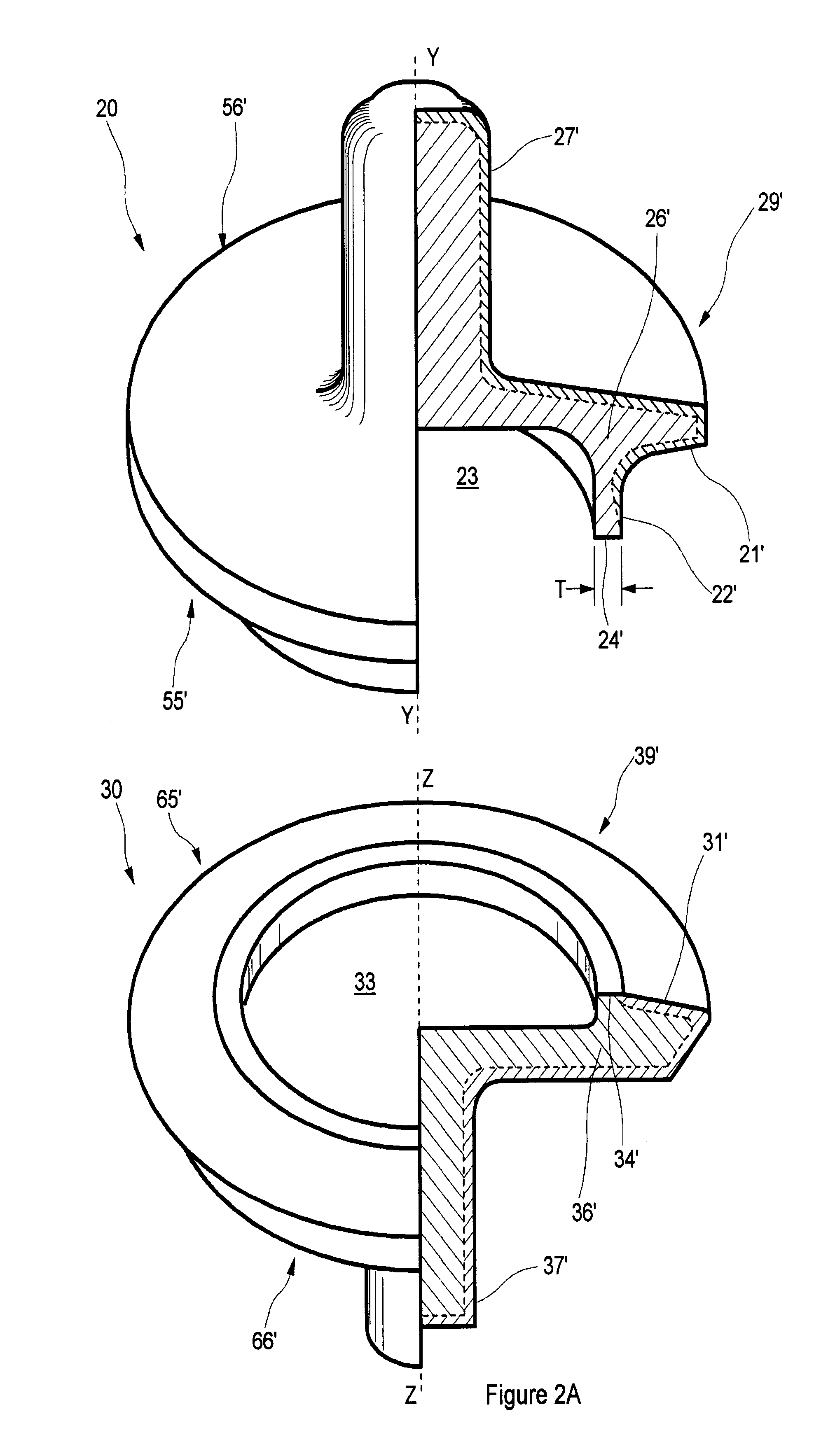
Finally, the threads often used to secure a retention plate to a valve body are both expensive to
machine and, because portions of the threads are relatively thin, they demand special protection during heat treatment.
Unfortunately then, even though forged valve bodies having integral seal retention groves, as in the Channel-Beam design, are inherently stronger than designs requiring a removable seal retention plate, they are generally heavier, more expensive to make, and prone to failure due to seal movement and / or out-of-round seals.
Additionally, cast valve bodies generally have lower impact strength compared to similarly shaped forgings.

