Watertight connector

Active Publication Date: 2005-06-02
SUMITOMO WIRING SYST LTD
View PDF10 Cites 13 Cited by
  • Summary
  • Abstract
  • Description
  • Claims
  • Application Information

AI Technical Summary

Benefits of technology

[0007] The invention relates to a watertight connector that has a housing formed with cavities. A resilient plug is mounted to a rear end of the housing and has at least one wire insertion hole that correspond to at least one cavity. The connector also includes at least one terminal fitting that is secured to an end of a wire. A main portion of the terminal fitting projects forward of the wire and has an outer shape that is larger than the outer diameter of the wire. A sealing plug is mounted on the wire behind the

Problems solved by technology

Accordingly, the main portion of the female terminal fitting may not be easily insertable through the wire insertion hole.
Forcible insert

Method used


Image

  • Watertight connector
  • Watertight connector
  • Watertight connector

Examples


Embodiment Construction

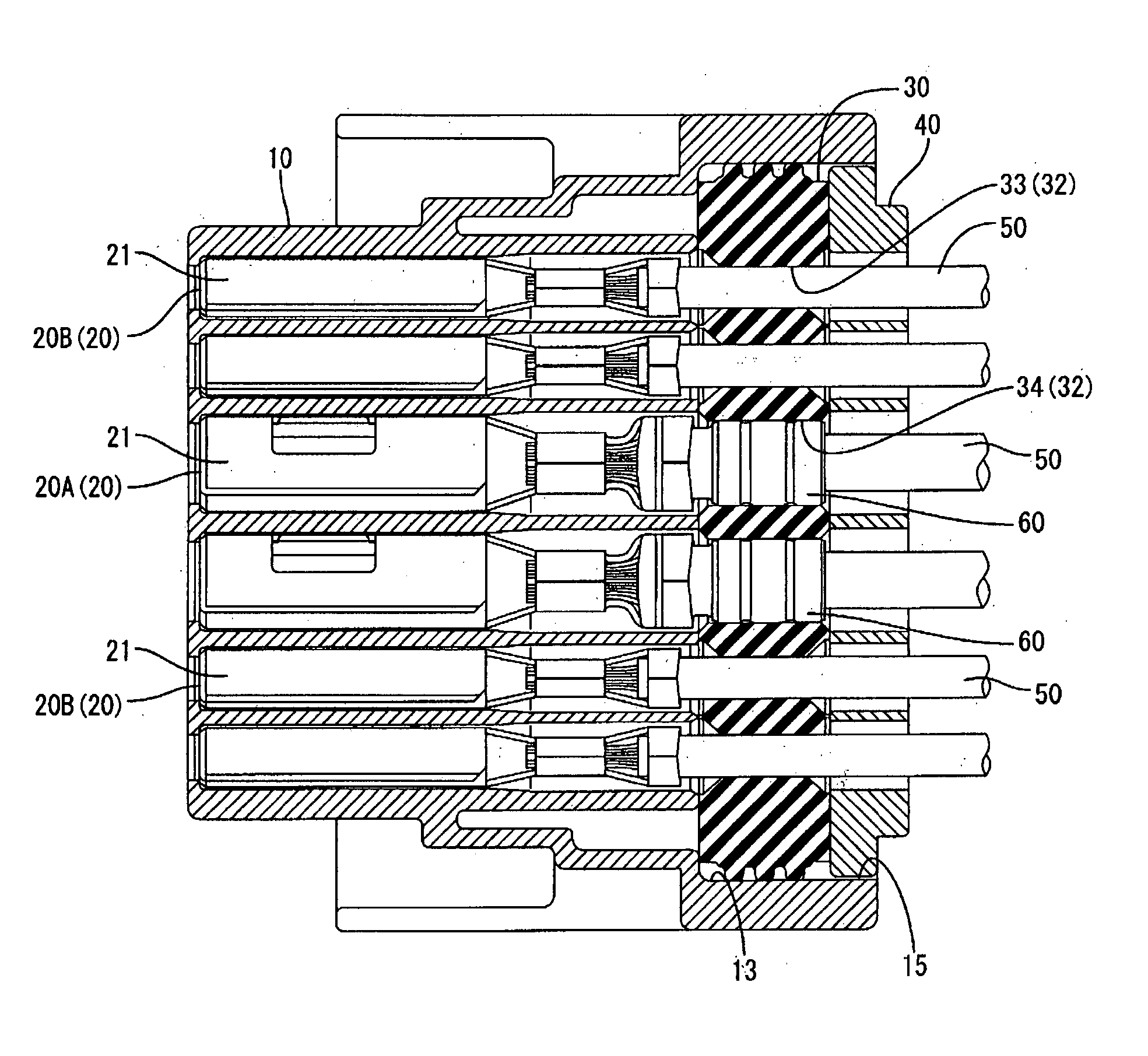
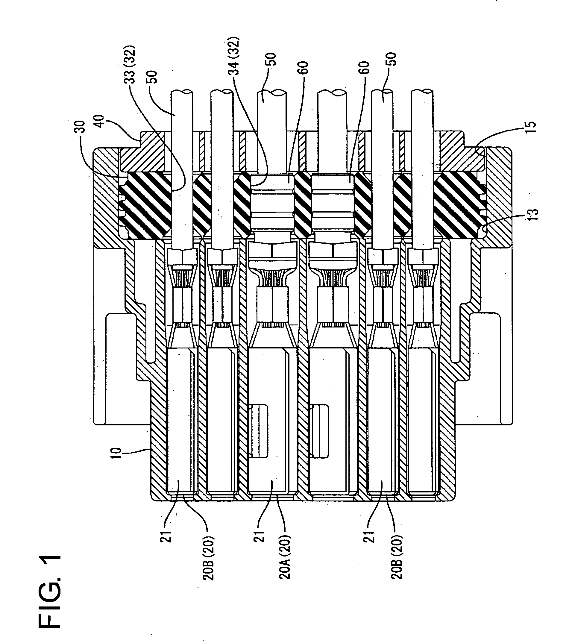
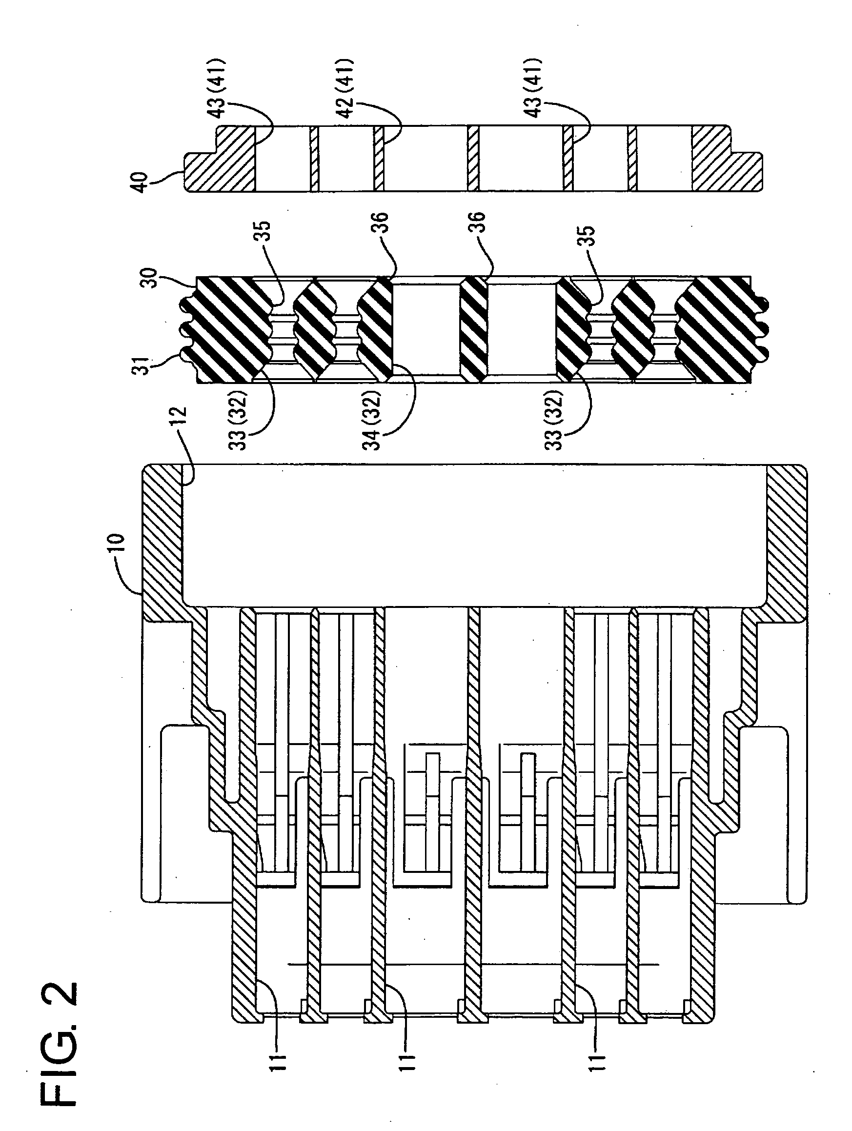
[0017] A female watertight connector according to the invention is described with reference to FIGS. 1 to 6. The female watertight connector includes a female housing 10 that has a plurality of female terminal fittings 20, a one-piece rubber plug 30 and a rubber-plug holder 40. In the following description, the left side in FIG. 1 is referred to as the front.

[0018] As shown in FIGS. 5 and 6, the female terminal fittings 20 have different sizes, but substantially identical construction. Specifically, each female terminal fitting 20 is formed by press-forming an electrically conductive metal plate and has opposite front and rear ends. A rectangular tubular main portion 21 is formed at the front end of the female terminal fitting 20. A contact tongue (not shown) is formed in the main portion 20 for contacting a tab of a mating male terminal fitting (not shown). A wire barrel 22 and an insulation barrel 23 are coupled integrally behind the main portion 21 in this order. The female term...


PUM


Abstract

A one-piece rubber plug (30) of the hybrid type is mounted at a rear side of a female housing (20). Wire insertion holes (32) of the rubber plug (30) include large-diameter portions (34) and small-diameter portions (33). The outer circumferential surfaces of sealing plugs (60) corresponding to larger terminals (20A) are resiliently brought into close contact with the inner circumferential surfaces of the large-diameter portions (34), whereas the outer circumferential surfaces of wires (33) are resiliently brought into close contact with the outer circumferential surfaces of wires (50) corresponding to small terminals (20B).

Description

BACKGROUND OF THE INVENTION [0001] 1. Field of the Invention [0002] The present invention relates to a watertight connector. [0003] 2. Description of the Related Art [0004] Japanese Unexamined Patent Publication No. 2002-343492 discloses a watertight connector with a housing that has a plurality of cavities for accommodating female terminal fittings. A one-piece rubber plug is arranged at the rear of the cavities and has wire insertion holes that align respectively with the cavities. A holder is mounted behind the rubber plug and has terminal insertion openings that correspond respectively to the wire insertion holes. Each female terminal fitting is secured to the end of a wire and is inserted through a terminal insertion opening of the holder. The female terminal fitting then resiliently widens the wire insertion hole and penetrates the rubber plug. Finally, the female terminal fitting is pressed into the respective cavity. The rubber plug returns resiliently after the female termi...

Claims


Application Information

Patent Timeline
IPC IPC(8): H01R13/52
CPCH01R13/5208
Inventor ITO, OSAMU
Owner SUMITOMO WIRING SYST LTD
Why Eureka
Try Eureka