Method for dynamic determination of time constants, method for level detection, method for compressing an electric audio signal and hearing aid, wherein the method for compression is used

a dynamic determination and time constant technology, applied in the direction of transducer casings/cabinets/supports, electrical transducers, electrical apparatus, etc., can solve the problem of insufficient amplification of weak signals

Active Publication Date: 2005-08-11
OTICON
View PDF7 Cites 17 Cited by
  • Summary
  • Abstract
  • Description
  • Claims
  • Application Information

AI Technical Summary

Benefits of technology

[0035] In a further aspect of the invention a method for compressing an electric audio signal is provided, which uses level detector method as defined above. Such a compression method wi

Problems solved by technology

Heavy sound levels of short duration will quickly excite the peak value detecting circuit and provide a quick gain reduction, but after a heavy sound of longer duration which dis

Method used


Image

  • Method for dynamic determination of time constants, method for level detection, method for compressing an electric audio signal and hearing aid, wherein the method for compression is used
  • Method for dynamic determination of time constants, method for level detection, method for compressing an electric audio signal and hearing aid, wherein the method for compression is used
  • Method for dynamic determination of time constants, method for level detection, method for compressing an electric audio signal and hearing aid, wherein the method for compression is used

Examples


Embodiment Construction

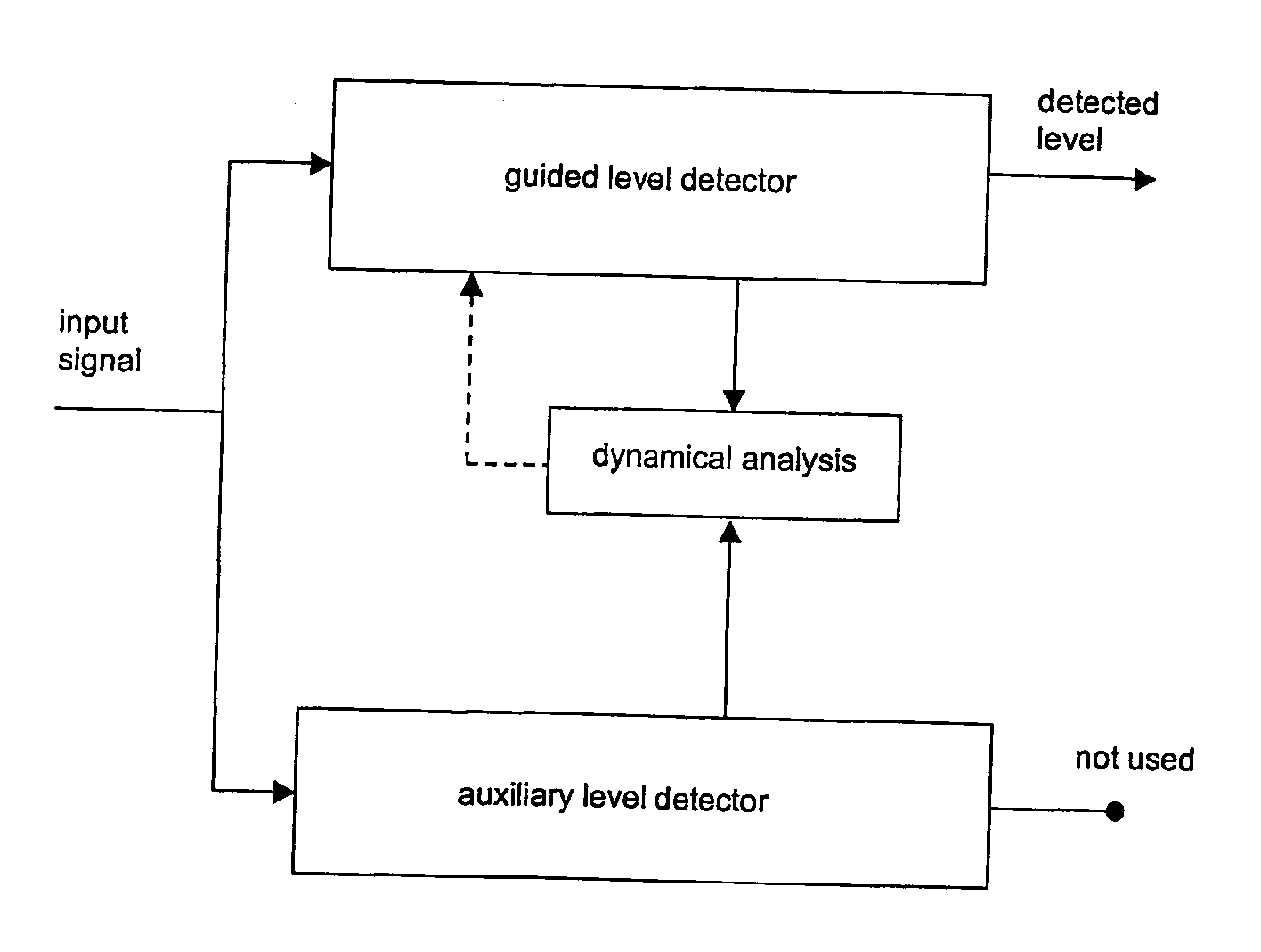
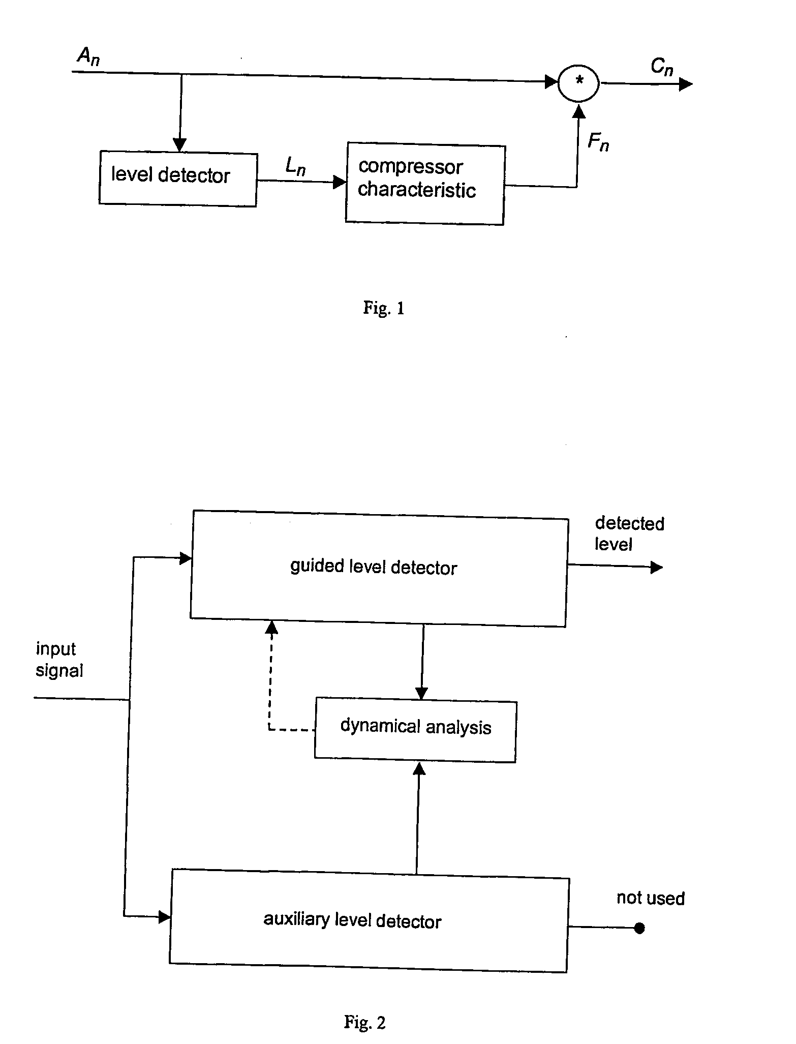
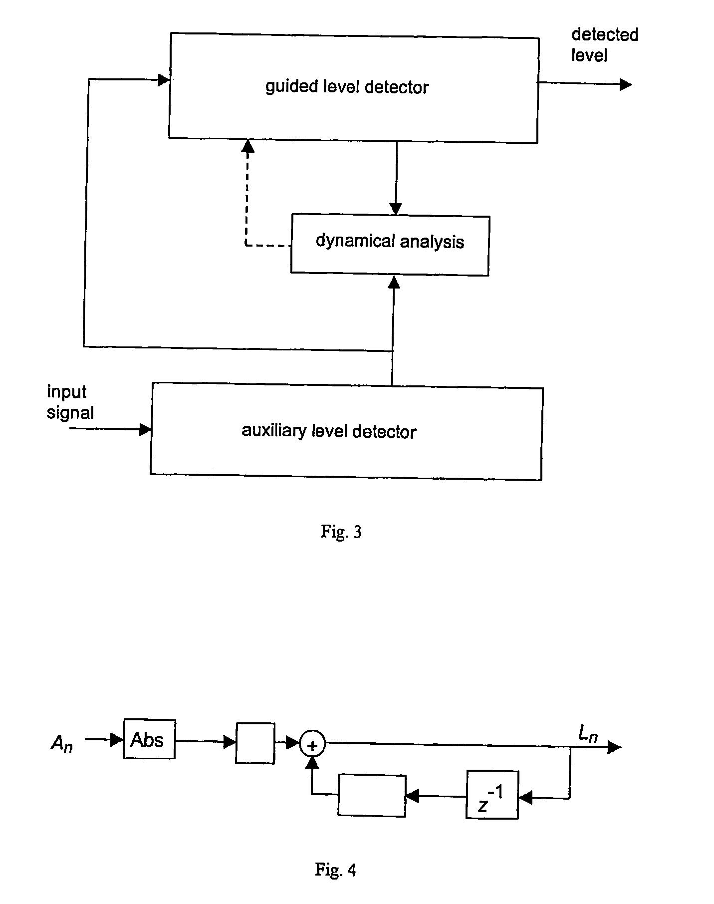
[0045] The method for level detection according to the invention is displayed in FIG. 2. The input signal is analyzed in two parallel level detectors: an auxiliary level detector and a guided level detector. The time constant of the auxiliary level detector is fixed. The time constant of the guided level detector is determined by the dynamical analysis. The dynamical analysis is based on the output of the auxiliary level detector and the output of the guided level detector. The output of this analysis determines at all times the time constant of the guided level detector and thus the dynamical behavior of the level detector as a whole.

[0046] In an embodiment of the invention, the auxiliary and the guided level detector are implemented as a simple level detector as shown in FIG. 4. In the simple level detector, the input signal is rectified and filtered by a first order IIR filter. The single coefficient f of this IIR filter is directly related to the time constant τ of the simple l...


PUM


Abstract

The invention provides a method for dynamic determination of time constants to be used in a detection of the signal level of an input signal of unknown level in an electric circuit, comprising the following steps:—feed the input signal through an auxiliary level detection means that is reacting faster to changes in the input sound signal level than the detection of the signal level as a whole,—feed either the input signal or the output of the auxiliary level detection means through a guided level detection means, which is arranged with a guided time constant, and where the guided level detection means outputs an estimate of the level of the input signal,—analyze the outputs of the auxiliary and the guided level detector means, determine the time constant of the guided level detection means based on this analysis.

Description

AREA OF THE INVENTION [0001] Compressors can be found in most modern hearing instruments. They provide a number of possible benefits for the hearing aid user: [0002] Loudness compensation, the task of loudness compensation compressors is to crush the dynamics of the acoustical environment into the dynamics of the hearing impaired. [0003] Reduction of upward spread of masking, low-frequency components of noise do not only mask low-frequency speech cues, but also reduce the audibility of high-frequency cues due to the upward spread of masking. A frequency-dependent compression can reduce this effect and thus increase speech intelligibility in noisy environments. [0004] Listening comfort, compressors that reduce the level of loud sounds also increase the listening comfort without sacrificing the audibility of soft sounds. [0005] Output-limiting systems, an output-limiting compressor is a good choice, since peak-clippers introduce a substantially greater amount of distortion. [0006]...

Claims


Application Information

Patent Timeline
IPC IPC(8): H04R25/00
CPCH04R25/502H04R25/356
Inventor NEUMANN, JOACHIM
Owner OTICON
Why Eureka
Try Eureka