Metal detector for use with conductive media

a metal detector and conductive media technology, applied in the field of metal detectors, can solve the problems of not having decayed enough to be insignificant, and achieve the effects of short time constant, high amplification, and high sensitivity to targets

Inactive Publication Date: 2013-07-25
WESTERSTEN ALLAN
View PDF2 Cites 4 Cited by
  • Summary
  • Abstract
  • Description
  • Claims
  • Application Information

AI Technical Summary

Benefits of technology

[0005]The present invention provides a solution to the problem of input amplifier overload by minimizing the background signal amplitude at its very source, making it possible to maintain high amplification in the input amplifier, which results in higher sensitivity to targets.
[0006]The operating principle of the detector is based on the observation that when a very fast magnetic field step function is imposed on a target, one with a short time constant responds more than one with a long time constant.
[0007]Background signals usually have shorter time constants than the targets to be detected.
[0008]Selectively minimizing the amplitude of the background signal without materially affecting the target signal is made possible by the use of a transmitter coil energizing wave form that combines a long charging interval for a target and a very short charging interval of the opposite polarity that essentially cancels eddy currents with a short time constant in the medium in which a target is located.
[0009]The salient distinction between the present invention and prior-art metal detectors is the inclusion of a short magnetic field step function at the end of a conventional charging interval of targets and the means required to regulate the magnitude of said step function, so that the background signal is essentially canceled. As the target signal amplitude is also lowered to some degree by said short magnetic step function, additional means are included in the invention to restore the sensitivity to targets with long time constants.

Problems solved by technology

The background signals pose a problem mainly because the ground or a load on a conveyor belt has a very large volume compared to a target to be detected and despite the short time constant of the background signal, it will not have decayed enough to be insignificant at a time when a target signal is sampled.

Method used


Image

  • Metal detector for use with conductive media
  • Metal detector for use with conductive media
  • Metal detector for use with conductive media

Examples


Embodiment Construction

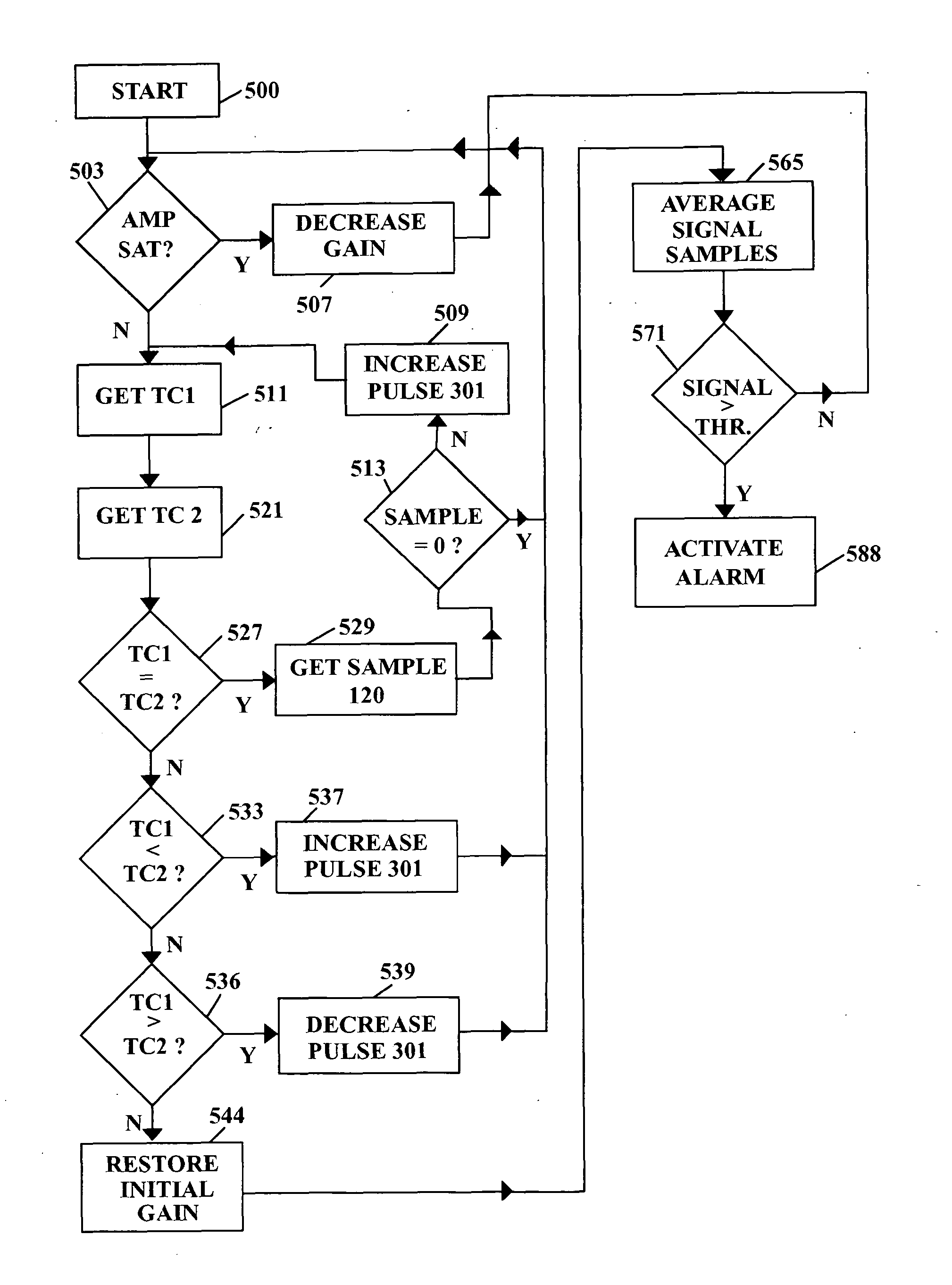
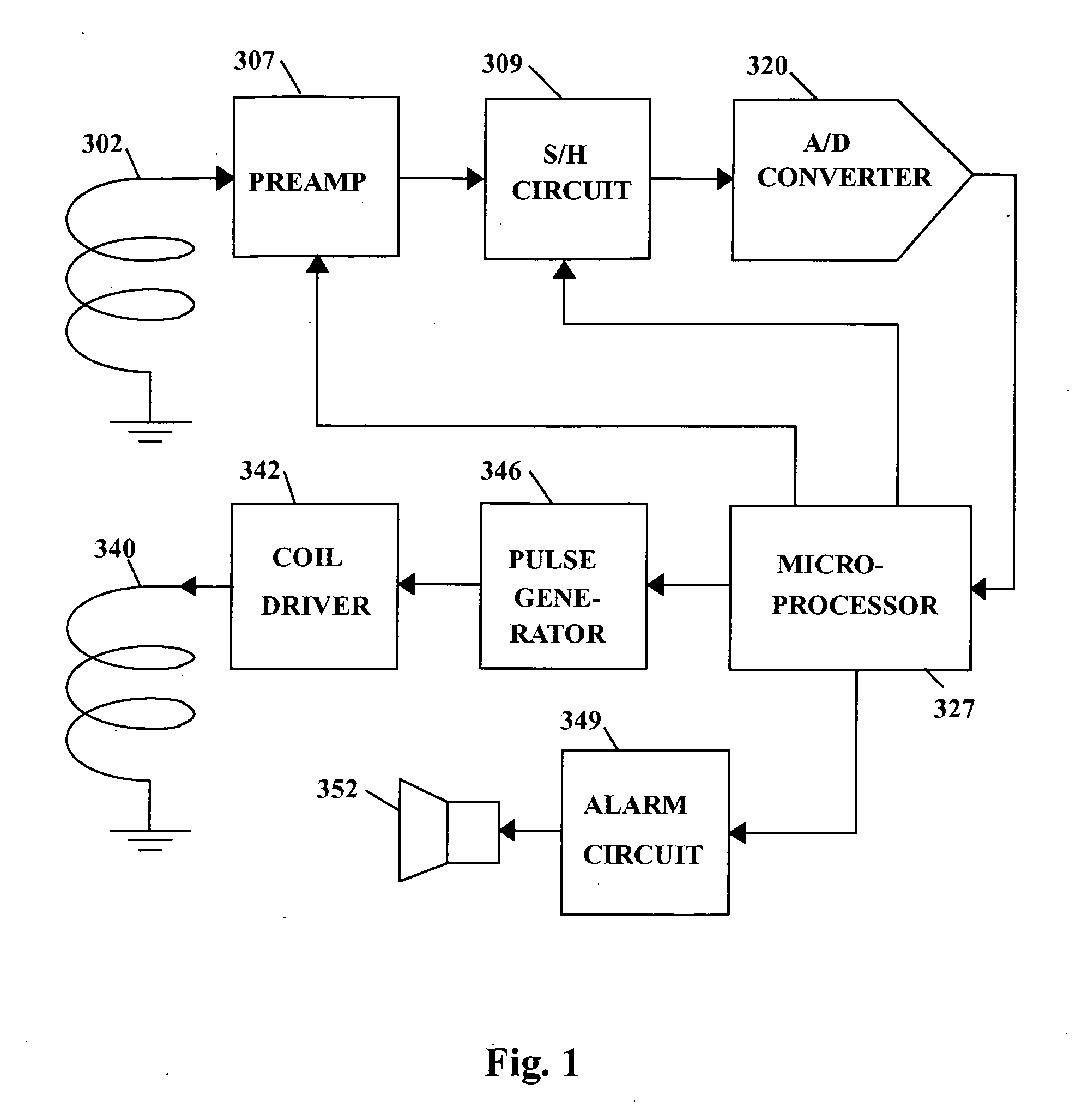
[0015]Microprocessor 327, shown in FIG. 1, delivers a digitally stored waveform to pulse generator 346, which in turn activates coil driver 342 that converts the voltage waveform to a current with a corresponding shape, imposing it on transmitter coil 340.

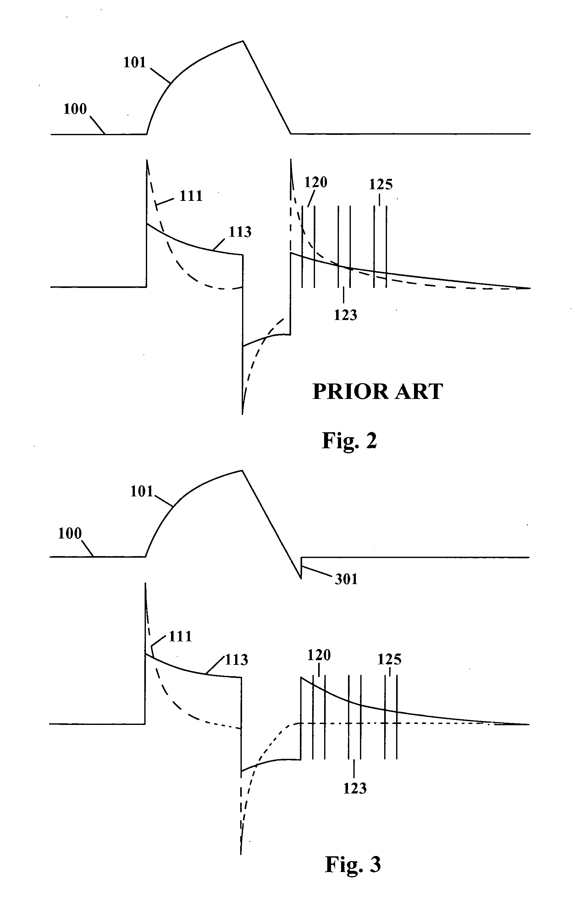
[0016]The magnetic field emanating from transmitter coil 340 engenders eddy currents in a target and its surrounding medium. The magnetic field generated by said eddy currents induces voltages in receiver coil 302. After the termination of the coil pulse, the eddy currents in the target and the surrounding medium decay toward zero, each according to its own time constant. At any point in time, the voltages captured by receiver coil 302 are summed algebraically, and in the state-of-the-art metal detector they are inextricably intermingled.

[0017]In FIG. 2, trace 111 shows a voltage generated by the background medium and trace 113 shows the voltage generated by a target. The voltage with the shorter time constant is the background sig...


PUM


Abstract

A pulse-induction type metal detector using a transmitter coil energizing pulse that selectively reduces the amplitude of background signals from conductive soils, ores and salt water. The detector can be operated with higher amplification of the received signals than conventional detectors, without driving the input amplifier into saturation. This makes it possible to detect land mines, tramp metal and gold in media whose characteristics make detection with conventional metal detectors difficult.

Description

TECHNICAL FIELD OF THE INVENTION[0001]This invention relates to metal detectors and specifically to detectors that are optimized for use with conductive media. The technology disclosed is applicable to pulse-induction type metal detectors.BACKGROUND OF THE INVENTION[0002]When metal detectors are used to detect targets in conductive media, the background signal amplitude may be so high that the input amplifier of the detector is driven into saturation.When the gain of the input amplifier is lowered to make the detector operative, the sensitivity to targets is lowered correspondingly.[0003]In prior art metal detectors, the background signals are dealt with by sampling the received signals at various times and by combining said samples algebraically, using multiplication factors that cause the background signals to essentially cancel.[0004]US Application No. 20100148960 by Candy is an example of such technology. The above approach does not address the basic problem of the input amplifi...

Claims


Application Information

Patent Timeline
Patent Type & Authority Applications(United States)
IPC IPC(8): G01V3/11
CPCG01V3/15G01V3/104
Inventor WESTERSTEN, ALLAN
Owner WESTERSTEN ALLAN
Why Eureka
Try Eureka