Method and apparatus of using optical distortion in a directed countermeasure system to provide a variable field of view

a countermeasure system and optical distortion technology, applied in the field of optical distortion directed countermeasure systems, can solve the problems of system not finding incoming missiles off-axis by more than a couple of degrees, time-consuming search mode, and inability to provide a pod of sufficient dimensions to house such a telephoto lens, etc., to achieve low cost, high target fidelity, and operation more reliable

Active Publication Date: 2006-07-27
BAE SYST INFORMATION & ELECTRONICS SYST INTERGRATION INC
View PDF3 Cites 43 Cited by
  • Summary
  • Abstract
  • Description
  • Claims
  • Application Information

AI Technical Summary

Benefits of technology

[0037] It will be appreciated that the subject invention provides the capability of going from target acquisition to target track modes in one smooth, continuous operation without field-switching delays and uncertainties. The optics are simpler, less expensive and more robust than those associated with a two field-of-view system. Moreover, in the subject system there are no moving parts and the operation is more reliable.
[0038] In summary, a single, hard-mounted set of optics is utilized to replace a two field-of-view system for directed countermeasures. It includes within one continuous but distorted field of view the capability to detect, acquire and characterize targets at the edge of the field while precisely tracking with high target fidelity at the field center. With multiple targets, both tracking of a primary target and acquisition of a secondary target can occur simultaneously, greatly improving countermeasure effectiveness.

Problems solved by technology

The problem with the fixed field of view was that in order to be able to find a threat one needed a wild field of view; but in order to track the threat one needed a relatively small field of view.
If one were limited to a narrow field of view for the resolution necessary for tracking, the system might not find incoming missiles off-axis by more than a couple of degrees.
This search mode, however, was time consuming, leading to the present two field-of-view system described below.
The problem with fixed field-of-view optics had been the tradeoff between the field of view being too small to acquire a target versus being too large to be able to accurately determine its position in space.
In short, it was impractical to provide a pod of sufficient dimensions to house such a telephoto lens and for this reason, current two field-of-view systems are now prevalent.
The result is magnification and better resolution, but at the cost of a narrow field of view unsuitable for searching.
The problem with such two-field-of-view systems is that the switching from the search phase to the tracking phase and back again takes a relatively long period of time, long relative to the time of flight of the attacking missile.
Not only were solenoids or motors used to drive the movable assembly into and out of position along the optical axis of the objective lens, alignment problems could occur during this electromechanical actuation process.
Thus, for instance, if the optics were to initially aligned to within tight tolerances, oftentimes the movable assembly threw the entire system out of alignment.
More importantly, should the solenoid or mechanical actuation system fail at any time within the critical engagement period, one could not track the threat and the countermeasure system could fail to countermeasure the incoming missile.
This cannot be done with field switching systems that either acquire or track but do not do both simultaneously.

Method used


Image

  • Method and apparatus of using optical distortion in a directed countermeasure system to provide a variable field of view
  • Method and apparatus of using optical distortion in a directed countermeasure system to provide a variable field of view
  • Method and apparatus of using optical distortion in a directed countermeasure system to provide a variable field of view

Examples


Embodiment Construction

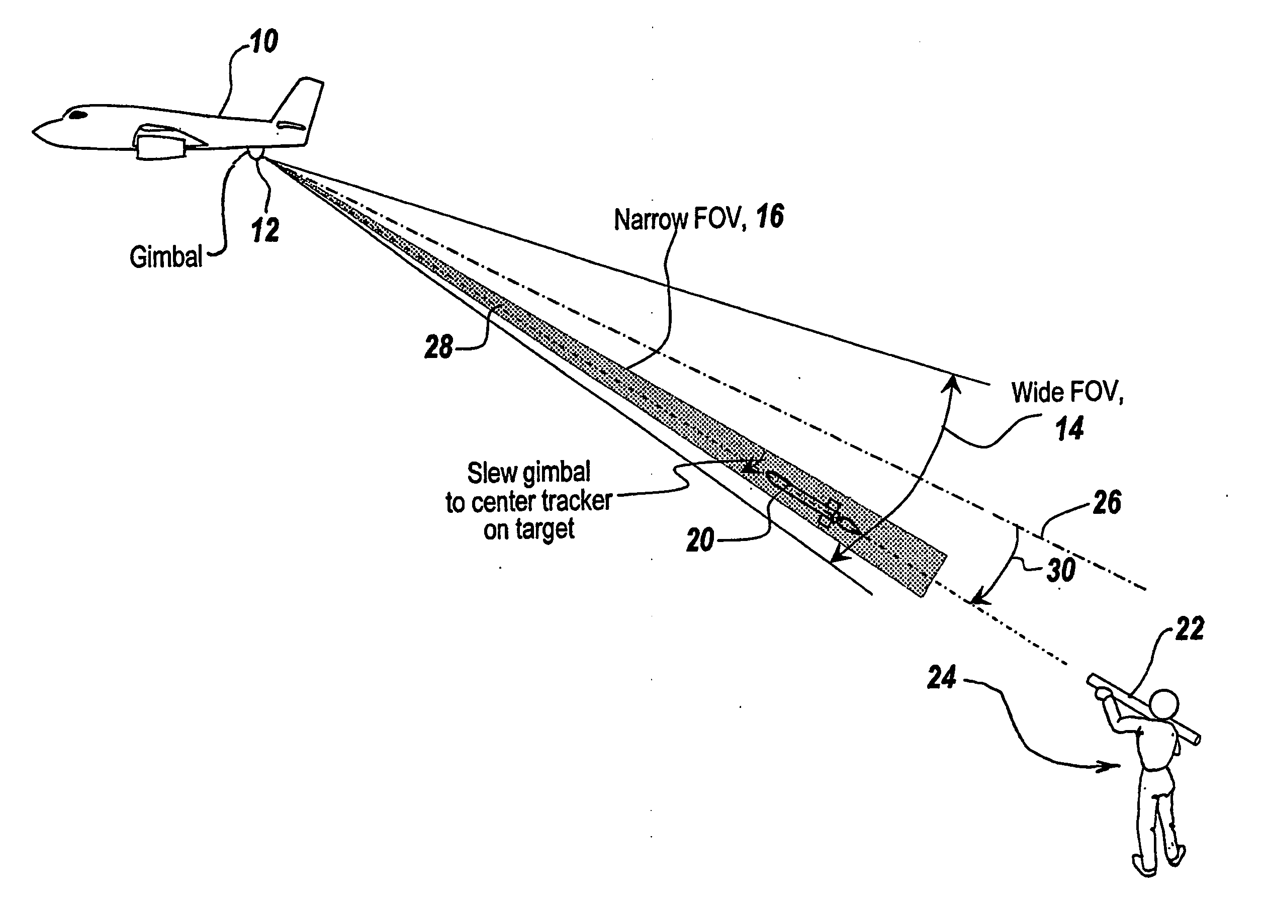
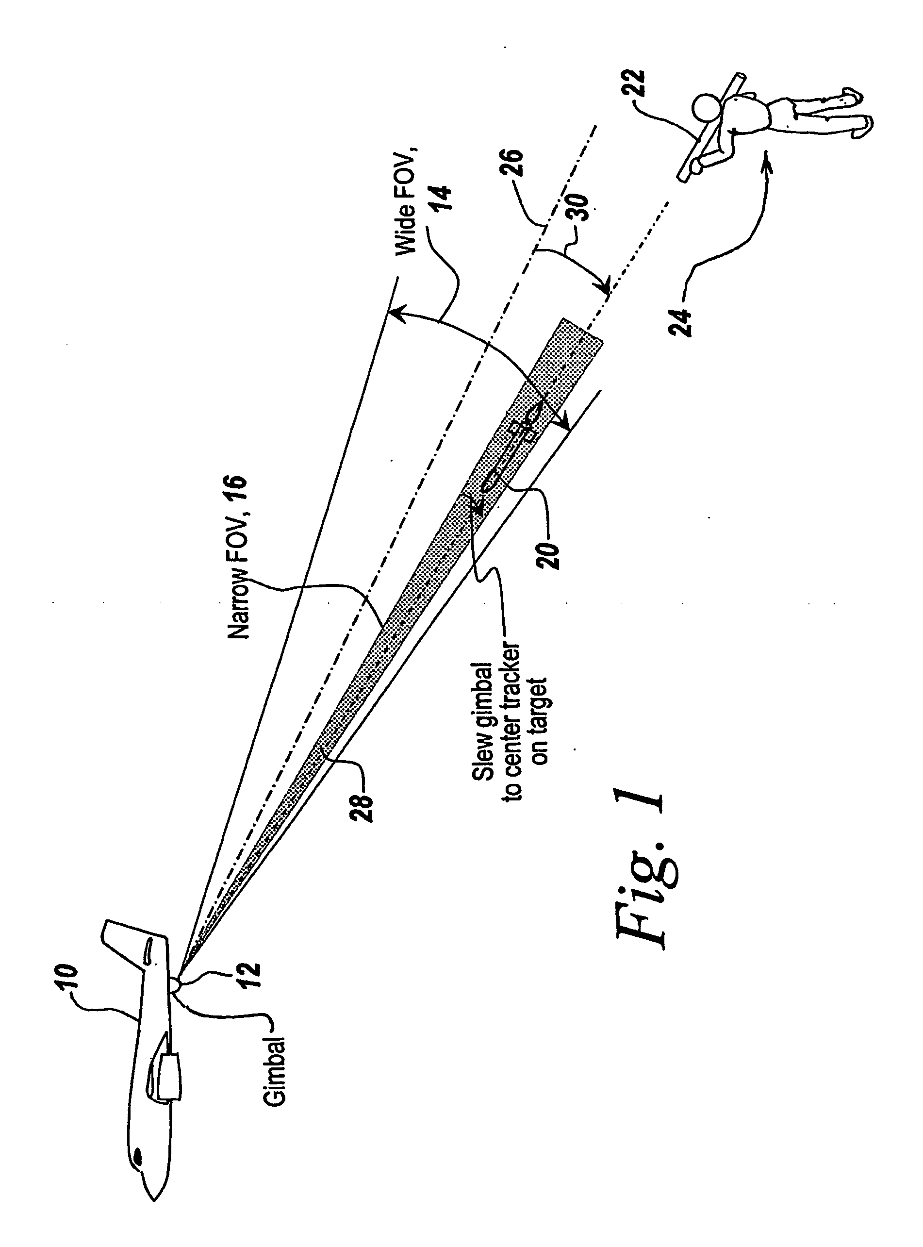
[0048] Referring now to FIG. 1, a typical scenario is envisaged in which an aircraft 10 has a gimbaled countermeasured system 12 which has internal optics (not shown in this figure) that establish a two field-of-view system. During the search mode, a wide field of view 14 is illustrated which in one embodiment subtends an angle of 30°, whereas in a track mode, the system switches to a narrow field of view 16 subtending 3° so as to be able to track any detected missile.

[0049] Here a missile 20 is shown having been launched from a shoulder-fired launcher 22 by an individual 24 towards aircraft 10.

[0050] At the time the missile is detected as having been launched, the optical center line of the countermeasure system is that which is shown by a dotted line 26 and it is around this optical center line that the narrow field of view extends.

[0051] When launched, missile 20 is directed along a flight path illustrated by dotted line 28 towards aircraft 10. When the missile is detected dur...


PUM


Abstract

A single, hard-mounted set of optics is utilized to replace a two field-of-view system for directed countermeasures. It includes within one continuous but distorted field of view the capability to detect, acquire and characterize targets at the edge of the field while precisely tracking with high target fidelity at the field center. With multiple targets, both tracking of a primary target and acquisition of a secondary target can occur simultaneously, greatly improving countermeasure effectiveness.

Description

FIELD OF THE INVENTION [0001] This invention relates to optical countermeasure systems and more particularly to the use of fixed optics and optical distortion to provide a wide field of view during a search mode and a narrowed field of view during a tracking mode. BACKGROUND OF THE INVENTION [0002] In directed countermeasure systems, an incoming missile is detected by an IR focal plane array in a target acquisition mode and when detected is tracked in a tracking mode. In the target acquisition mode, it is important that the optics utilized in detecting the launch of, for instance, a shoulder-fired missile, have a relatively wide field of view so that incoming missiles will not escape the countermeasure system by being outside its field of view. For such a target acquisition, the lens assembly utilized has oftentimes been likened to a fisheye lens which in essence covers a wide field of view and is therefore capable of detecting targets over a wide area. [0003] Early countermeasure s...

Claims


Application Information

Patent Timeline
Patent Type & Authority Applications(United States)
IPC IPC(8): G01J1/20G01J1/44G01C21/02G01C21/24G02BG02B7/04G02B13/16G02B15/04G02B27/40G02B27/64H01J3/14H01J5/16H01J40/14
CPCG01S3/781G01S3/786G01S7/495G02B13/12G02B13/16G02B15/04G01C21/02G01C21/24G02B27/40H01J3/14
Inventor GUYER, ROBERT C.KIRKHAM, ANTHONY
Owner BAE SYST INFORMATION & ELECTRONICS SYST INTERGRATION INC
Why Eureka
Try Eureka