Feedback-Control Wearable Upper-Limb Electrical Stimulation Device

a technology of electrical stimulation device and upper limb, which is applied in the field of electrical stimulation device, can solve the problems of ineffective efficiency of conventional electrical stimulation rehabilitation, and achieve the effect of effectively controlling the affected limb

Active Publication Date: 2016-05-26
NATIONAL YUNLIN UNIVERSITY OF SCIENCE AND TECHNOLOGY
View PDF4 Cites 50 Cited by
  • Summary
  • Abstract
  • Description
  • Claims
  • Application Information

AI Technical Summary

Benefits of technology

[0011]The above-mentioned wearable upper limb electrical stimulation device with feedback control function, wherein the electromyography signal acquisition unit thereof comprises an electrical stimulation signal blocking circuit, a instrumentation amplifier, an amplifier circuit, a high-pass and low-pass filter and a voltage level shifter or clamp circuit. The electrical stimulation signal blocking circuit filters the electromyography signal from the interference by the electrical stimulation. The instrumentation amplifier performs a front-end amplification to the electromyography signal. The amplifier circuit increases an amplification ratio of the electromyography signal. The high-pass and low-pass filter filters the electromyography signal except for a setting range of the electromyography. The voltage level shifter or clamp circuit increases the voltage level of the electromyography signal. The above-mentioned wearable upper limb electrical stimulation device with feedback control function further comprises an analog-to-digital converter connected between the voltage level shifter or clamper circuit and the electromyography signal operation unit. The analog-to-digital converter transfers the electromyography signal outputted from the voltage level shifter or clamper circuit, and the electromyography signal operation unit receives the digitized electromyography signal, wherein the electromyography signal operation unit thereof comprises an interference operation unit, a comb filter and a subtraction circuit. After the interference operation unit filters pulses of the electrical stimulation in the electromyography signal, the comb filter gets the volitional electromyography signal from the electromyography signal. The subtraction circuit generates the stimulus electromyography signal by subtracting the volitional electromyography signal from the electromyography signal.
[0020]First, the present invention provides a suitable intensity of the electrical stimulation for a patient's limb to execute a specific movement or action, and provides an appropriate assist to the patient according to the received strength of the electromyography signal of the limb. Thus, the present invention not only activates the patient's partially disabled limb, but also can train the patient to have the ability to control the affected limb effectively.
[0022]Even though numerous characteristics and advantages of the present invention have been set forth in the foregoing description, together with details of the structure and features of the invention, the disclosure is illustrative only. Changes may be made in the details, especially in matters of shape, size and arrangement of parts within the principles of the invention to the full extent indicated by the broad general meaning of the terms in which the appended claims are expressed.

Problems solved by technology

As the result, the efficiency of the conventional electrical stimulation of rehabilitation is ineffective.

Method used


Image

  • Feedback-Control Wearable Upper-Limb Electrical Stimulation Device
  • Feedback-Control Wearable Upper-Limb Electrical Stimulation Device
  • Feedback-Control Wearable Upper-Limb Electrical Stimulation Device

Examples


Embodiment Construction

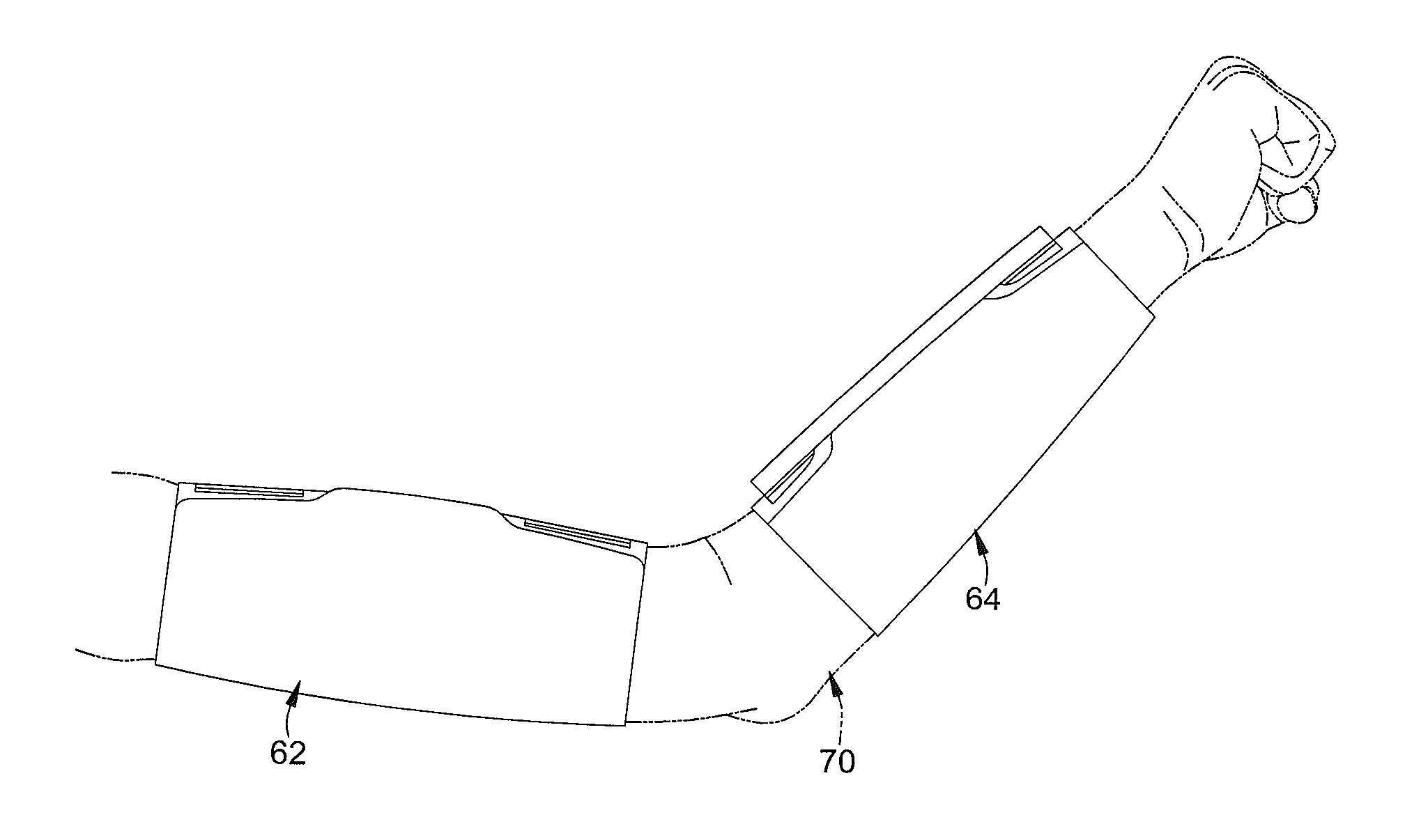
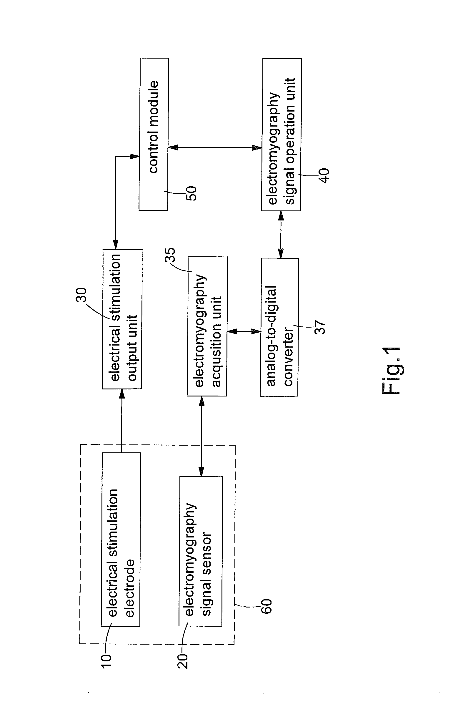
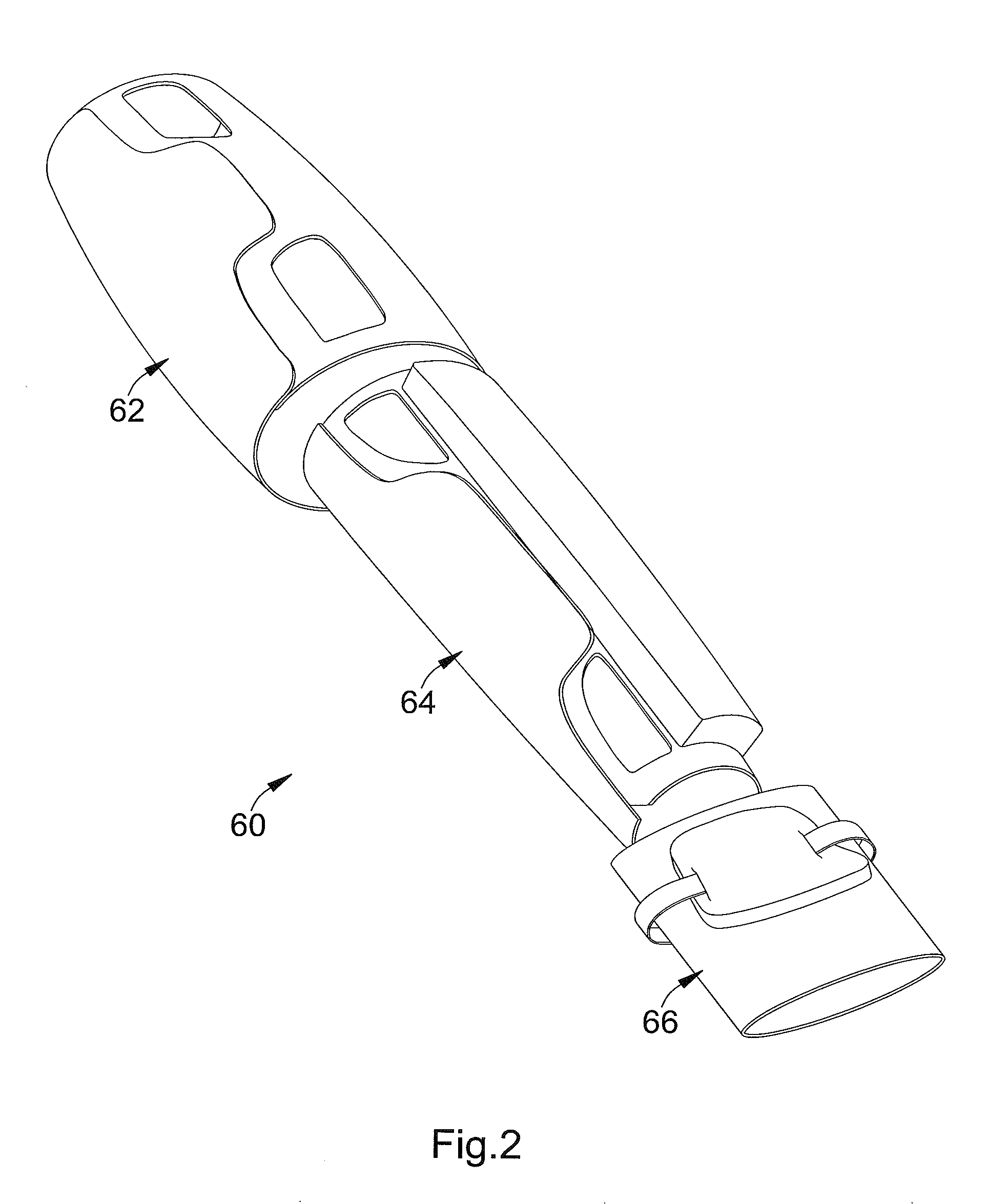
[0030]With reference to FIGS. 1 and 2, a preferred embodiment of a wearable upper limb electrical stimulation device with feedback control function in accordance with the present invention comprises multiple electrical stimulation electrodes 10, multiple electromyography signal sensors 20, an electrical stimulation output unit 30, an electromyography signal acquisition unit 35, an analog-to-digital converter 37, an electromyography signal operation unit 40, a control module 50 and a fixed brace 60.

[0031]With reference to FIGS. 3 to 5, FIG. 3 is an operational perspective view of the preferred embodiment of the present invention. FIG. 4 is an operational perspective view of the pasted position of the electrical stimulation electrode 10 and the electromyography signal sensor 20 of the preferred embodiment of the present invention. FIG. 5 is another operational perspective view of the pasted position of the electromyography signal sensor 20 in the preferred embodiment. Each one of the ...


PUM


Abstract

A feedback-control wearable upper-limb electrical stimulation device comprises a plurality of electrical stimulation electrodes (10), a plurality of myoelectric signal sensing elements (20), an electrical stimulation output unit (30), a myoelectric signal retrieval unit (35), a myoelectric signal operation unit (40), and a control module (50). Each electrical stimulation electrode (10) is adhered to or fixed in contact with a human trunk and applies an electrical stimulation signal to the neuromuscular system of the human trunk. Each myoelectric signal sensing element (20) is adhered to or fixed in contact with the human trunk at a corresponding position of the neuromuscular system of the human trunk where each electrical stimulation electrode (10) is disposed in an adhered manner. The electrical stimulation output unit (30) is connected to each electrical stimulation electrode (10) and provides an electrical stimulation signal. The myoelectric signal retrieval unit (35) is connected to each myoelectric signal sensing element (20) and receives a myoelectric signal. The myoelectric signal operation unit (40) is connected to the myoelectric signal retrieval unit (35). The control module (50) is electrically connected to the electrical stimulation output unit (30) and the myoelectric signal operation unit (40). The device first determines, according to the intensity of a myoelectric signal of a human trunk, the intensity of an electrical stimulation signal required for the human trunk to perform a specified action and gives a patient suitable assistance. Therefore, a local disabled limb of a patient can be effectively activated and a patient can be effectively exercised in controlling a diseased limb.

Description

BACKGROUND OF THE INVENTION[0001]1. Field of Invention[0002]This invention generally relates to an electrical stimulation device, and more particularly to an electrical stimulation device that can be used on the upper limbs of human and provides a feedback control function.[0003]2. Description of the Related Art[0004]People may lose the ability to control their limbs entirely or partially, which is caused by a stroke, certain diseases or trauma. In order to prevent the atrophy of affected limbs and recover the ability of controlling the limbs that are paralyzed or partially disabled, the physical treatment and rehabilitation should be given to the patient after diagnosed.[0005]For example, the stroke usually causes the hemiparesis or hemiplegia on the patient with different degrees and may be partial-ataxia or losing control on local neuromuscular system, which results in muscle weakness. So far, to give how much rehabilitation to the patient depends on the different degree of paral...

Claims


Application Information

Patent Timeline
Patent Type & Authority Applications(United States)
IPC IPC(8): A61N1/36A61B5/0488A61N1/04
CPCA61N1/36014A61N1/36003A61B5/0488A61N1/0452A61B5/4836A61B5/6824A61B5/6831A61B5/7203A61B5/725A61B2505/09A61N1/36031A61N1/36034A61B5/30A61B5/316A61B5/389
Inventor HSUEH, YA-HSINYEH, CHUN-YULO, HSIN-CHANG
Owner NATIONAL YUNLIN UNIVERSITY OF SCIENCE AND TECHNOLOGY
Why Eureka
Try Eureka