Relay device

Active Publication Date: 2005-10-13
RAKUTEN GRP INC
View PDF4 Cites 0 Cited by
  • Summary
  • Abstract
  • Description
  • Claims
  • Application Information

AI Technical Summary

Benefits of technology

[0020] According to the present invention, the effective a

Problems solved by technology

However, when the frame F1 transmitted to the main memory 12 via the DMA transmission includes deleted frames as described above, it can be said that using the bus BA1 to transmit the frame F1 is a waste of consumption of internal resources and judging by the CPU 11 after the DMA transmission, and effectively leads to resource availability deterioration due to the waste of the operatio

Method used


Image

  • Relay device
  • Relay device
  • Relay device

Examples


first embodiment

[0030] The preferred embodiment of the present invention will be explained below referring to a case in which a relay device according to a first preferred embodiment of the present invention is applied to a frame relay.

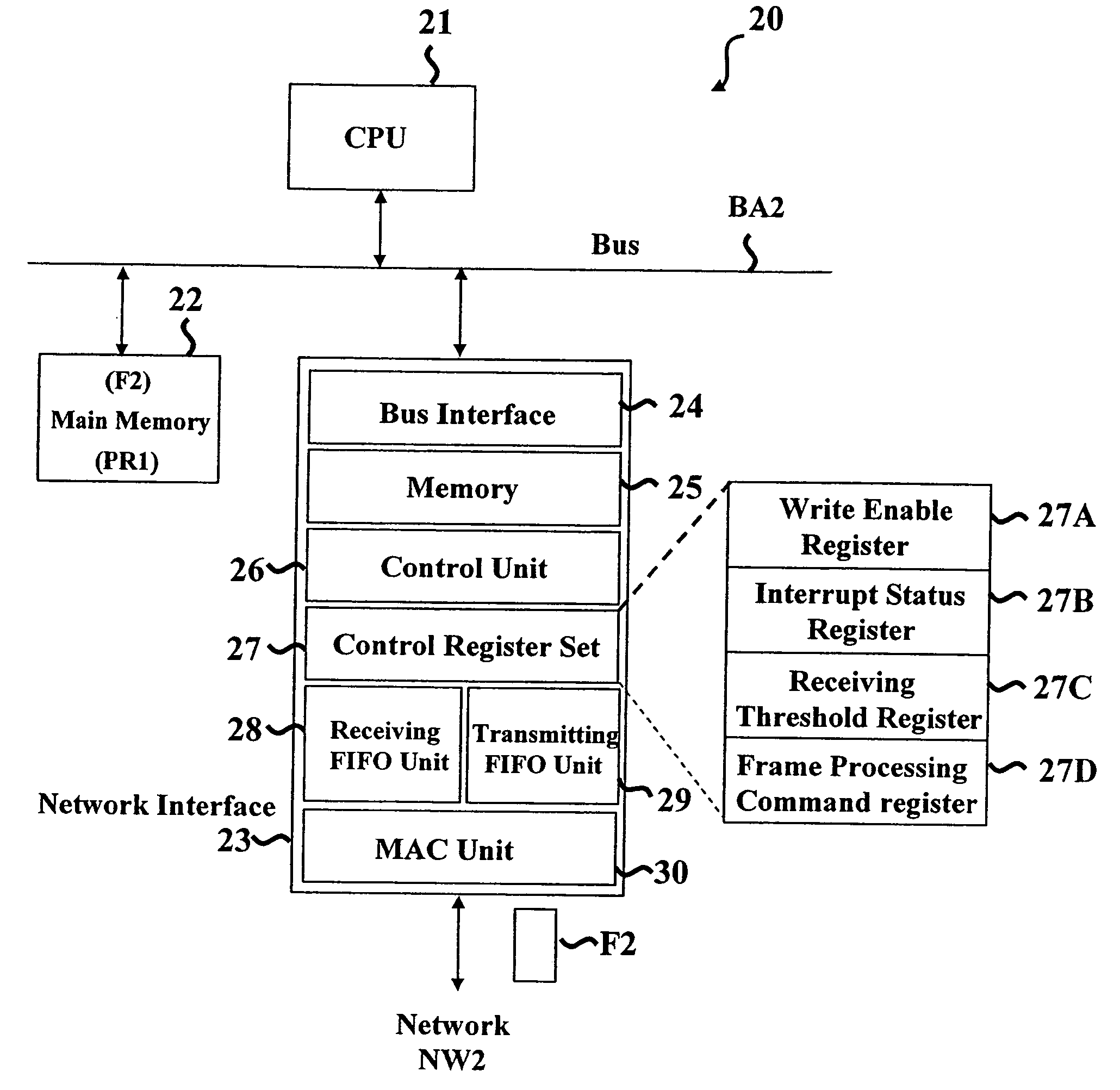
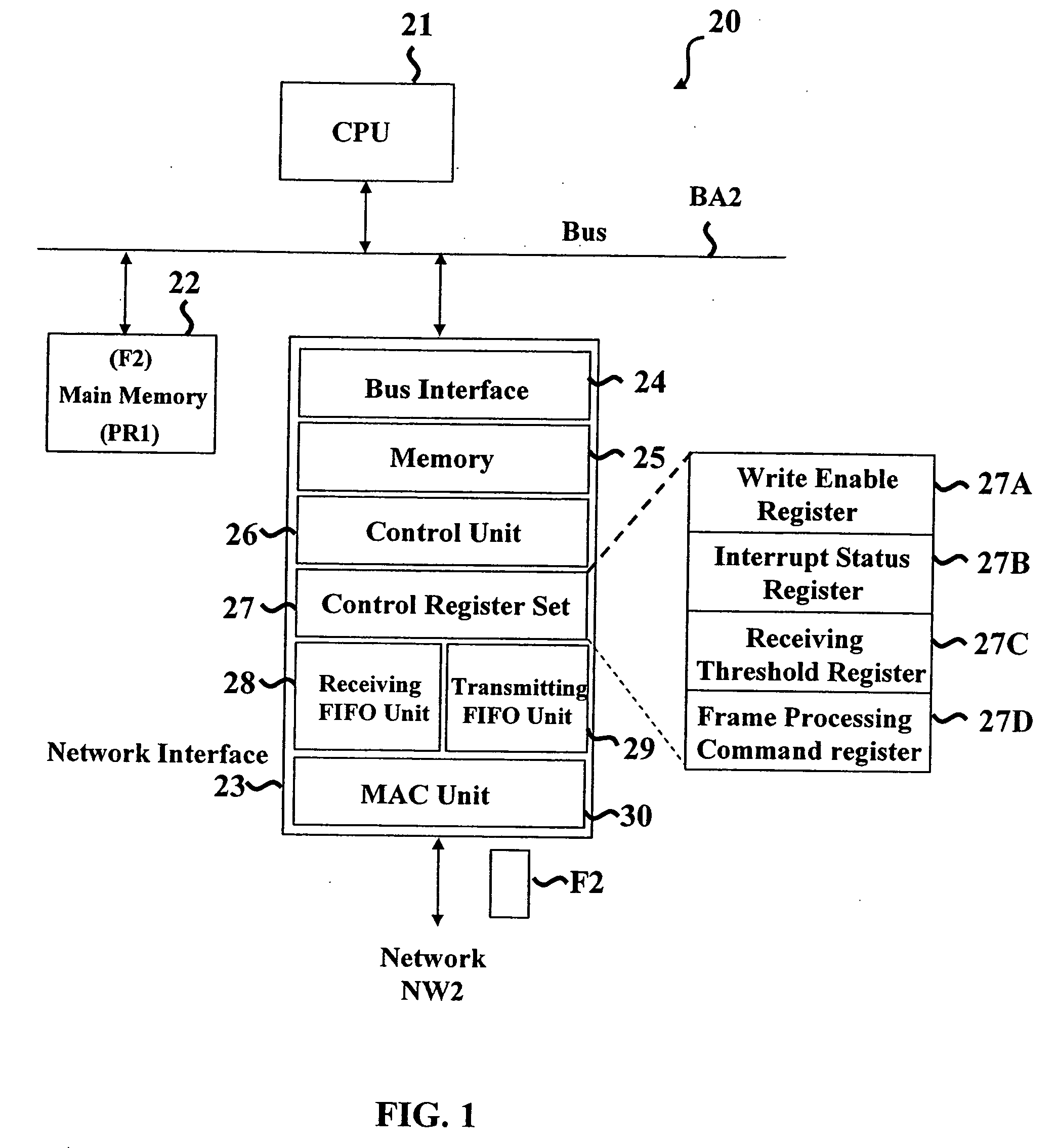
[0031] The configuration of a whole frame relay device 20 according to the first preferred embodiment the present invention is illustrated in FIG. 1. The frame relay device 20 can be regarded as a part of a personal computer (including a LAN card) or a part of a relay device, such as a layer-2 switcher or a rooter. If the frame device is considered a relay device, however, one or a plurality of networks other than the illustrated network interface 23 can exist.

[0032] In FIG. 1, the frame relay device 20 includes a CPU (Central Processing Unit or Main Control Unit) 21, a main memory 22, a network interface 23, and a bus BA2.

[0033] The bus BA2 herein is a transmission path in the frame relay device 20 installed to connect the CPU 21, the main memory 22, and the netw...

second embodiment

[0065] Only points of this embodiment that highlight significant differences from the first embodiment will be explained below. The configuration and behavior of the second embodiment of the present invention

[0066] A configuration of a whole frame relay device 40 according to a second preferred embodiment of the present invention is illustrated in FIG. 5. Since, in FIG. 5, each component labeled with the same signs 21-25, 28-30, BA2, and NW2 as those in FIG. 1 has the same or similar function according to the first embodiment of the present invention, detailed explanation thereof will be omitted.

[0067] A control circuit or unit 41 in FIG. 5 corresponds to the control unit 26 and the control register 42 corresponds to the control register 27. The control register 42 according to this embodiment of the present invention is also equipped with the registers 27A-27D as shown in FIG. 1, and consequently one of its functions is the same as the control register 27 according to the first e...

third embodiment

[0074] Only points of this embodiment that highlight significant differences from the first or the second embodiment will be explained below.

[0075] This embodiment of the present invention relates to a frame relay device having two network interfaces.

[0076] A whole configuration of a frame relay device 50 according to a third preferred embodiment of the present invention is illustrated in FIG. 5. The frame relay device 50 has two network interfaces shown in FIG. 6 that correspond to a relay device, for example, like the aforementioned layer-2 switch or rooter. Since in FIG. 6 the functions of components having the same signs 21-30, BA2, or NW2 as those in FIG. 1 have the same or similar functions to those of the first embodiment of the present invention, the specific explanation of the components thereof will be omitted.

[0077] The network interface 51 newly added to this embodiment of the present invention is connected to a network NW3, while the network interface 23 is connected...


PUM


Abstract

A data relay device transmitting received unit data has an external interface unit, a main control unit, where the received unit data are received from outside the data relay device and transmitted to the corresponding destination memory not through the main control unit. The external interface unit is equipped with memory in the external interface, the threshold setting unit, and the external control unit. The main control unit receiving the threshold receiving notice reads the information in the corresponding field of the received unit data stored in the memory in the external interface and judges whether the received unit data should be transmitted, or not. The main control unit deletes the received unit data judged to be unnecessary before the transmitting.

Description

BACKGROUND OF THE INVENTION [0001] 1. Field of the Invention [0002] The present invention generally relates to a relay device. More specifically, the present invention relates to a relay device, for example, that is preferably applied to transmission of a MAC frame received from a network within the relay device. [0003] 2. Background Information [0004] A conventional internal configuration of a relay device having a function of transmitting a MAC frame received from a network, is illustrated in FIG. 2. In the frame transmission device 10 illustrated in FIG. 2, a CPU (Central Processing Unit) 11 conducts the final control of each component. A network interface 13 receives a frame F1 from an external network NW1. The frame F1 then proceeds via a DMA (Direct Memory Access) transmission. During the DMA transmission, the network interface 13 transmits the frame F1 to the main memory 12 through the bus BA1 without the CPU 11. Consequently, even when the CPU 11 is conducting other processe...

Claims


Application Information

Patent Timeline
IPC IPC(8): G06F13/28H04J3/14H04L12/26H04L12/28H04L12/46H04L13/08
CPCH04L43/16H04L47/32H04L47/30H04L47/10
Inventor NAKAMURA, TOSHIHIKO
Owner RAKUTEN GRP INC
Why Eureka
Try Eureka