Automatic speed changer

a technology of automatic transmission and speed change, which is applied in the direction of mechanical equipment, transportation and packaging, and gearing, etc., can solve the problems of reducing the controllability of automatic transmission, increasing the shock of speed change, and compact automatic transmission, so as to improve the efficiency of automatic transmission and reduce the cost. , the effect of simplifying the manufacturing process

Active Publication Date: 2005-11-03
AISIN AW CO LTD
View PDF9 Cites 8 Cited by
  • Summary
  • Abstract
  • Description
  • Claims
  • Application Information

AI Technical Summary

Benefits of technology

[0016] Further, where three clutches are provided, compared to the case wherein three clutches are located on one side of the planetary gear unit, the construction of an oil line to provide oil to the hydraulic servos for these clutches can be made easily, the manufacturing process can be simplified and the costs can be brought down. Further, since the friction members and hydraulic servo of the third clutch can be made smaller, the third clutch can be located radially inward of the second brake, and the automatic transmission can be made more compact.
[0017] In one embodiment the present invention also includes a second brake for fixing the first rotary element which receives input of the decelerated rotation. The second brake and the third clu

Problems solved by technology

Further, if an elongated element must withstand the larger torque, it must be fabricated of a relatively thicker material which prevents making a more compact automatic transmission.
Further, because the weight of such a member would be increased, not only is the objective of a lightweight automatic transmission defeated, but also inertia (inertial force) would increase, reducing the controllability of

Method used


Image

  • Automatic speed changer
  • Automatic speed changer
  • Automatic speed changer

Examples


first embodiment

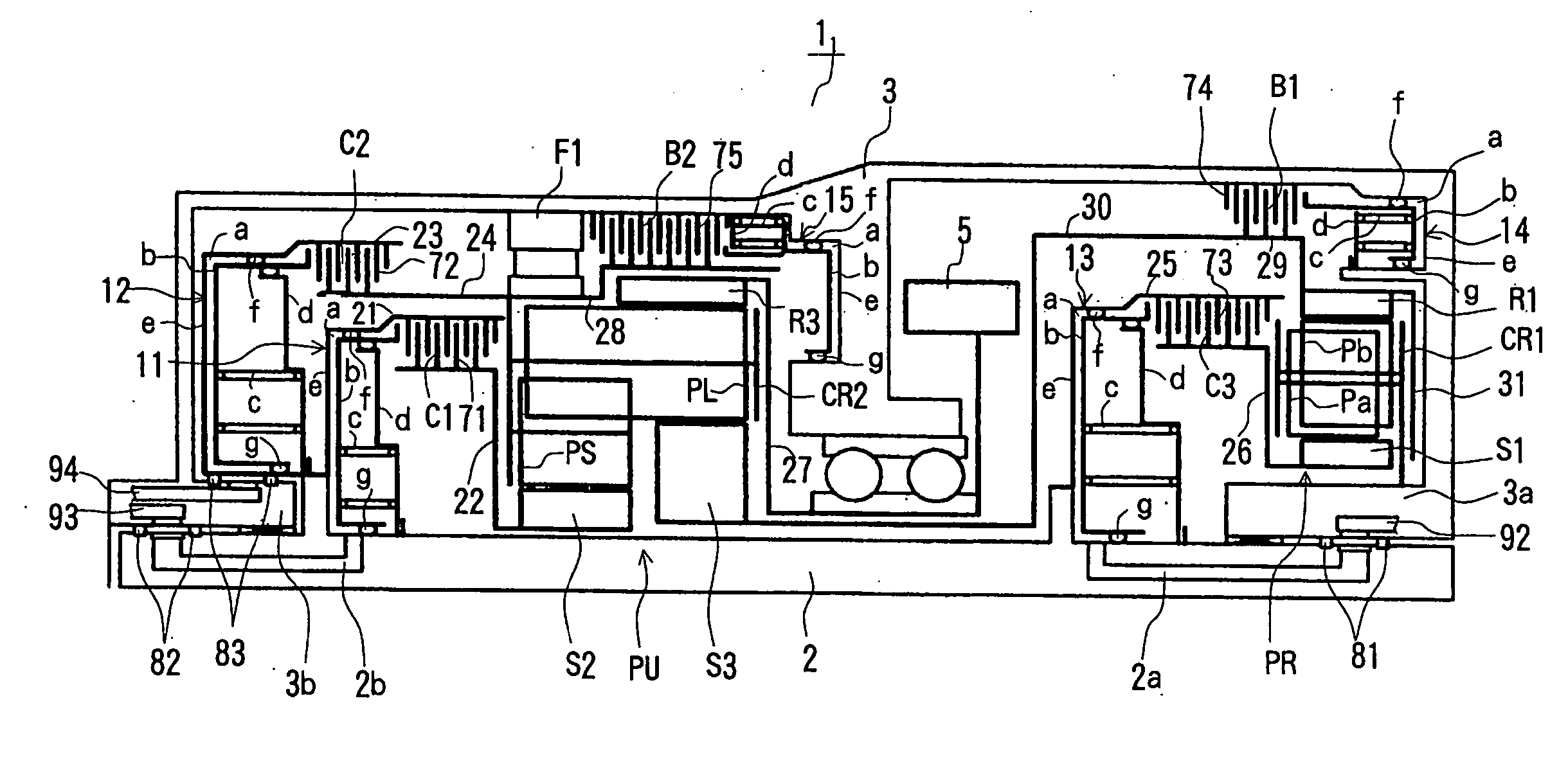
[0041] A first embodiment of the present invention will be described with reference to FIG. 1 through FIG. 3 below.

[0042] The automatic transmission of the first embodiment of the present invention as illustrated in FIG. 1 is particularly favorable for a FF (front engine, front wheel drive) vehicle, and has a torque converter housing, not illustrated, and a transmission case 3. Within the torque converter housing is a torque converter, not illustrated. The transmission case 3 houses an automatic transmission 1, a counter shaft unit (drive wheel transmission mechanism), not illustrated, and a differential unit (drive wheel transmission mechanism).

[0043] The torque converter is arranged, for example, with its axis centered on input shaft 2 of the automatic transmission 11, which is on the same axis as the output shaft of the engine (not illustrated), and the automatic transmission 11 is also centered on the axis of the engine.

[0044] The above-mentioned counter shaft unit includes a...

second embodiment

[0082] A second embodiment, which is a partial modification of the first embodiment, will be described with reference to FIG. 4. FIG. 4 is a schematic cross-sectional diagram of the automatic transmission of the second embodiment. Components of the second embodiment which are the same as those of the first embodiment are denoted by the same reference numerals in FIG. 4, and description thereof omitted, except for those components partially modified.

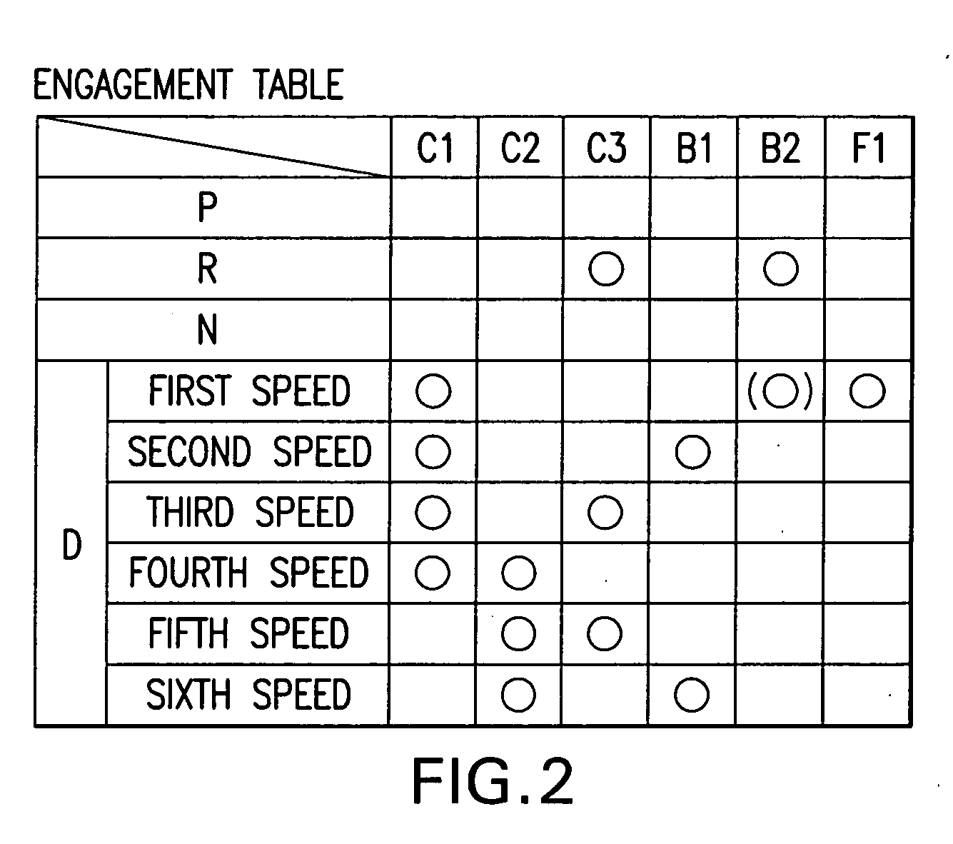
[0083] As FIG. 4 illustrates, the automatic transmission 12 of the second embodiment has the input and output ends the reverse of the automatic transmission 1 of the first embodiment (see FIG. 1). However, the operations establishing the first speed forward through the sixth speed forward and the first speed reverse are similar (see FIG. 2 and FIG. 3).

[0084] As shown in FIG. 4, in the automatic transmission 12 of the second embodiment, the first planetary gear unit PR and the clutch C3 are located at one axial end of the planetary gear ...

third embodiment

[0092] The third embodiment, which is a partial modification of the first embodiment will be described with reference to FIG. 5 through FIG. 7. Components of the third embodiment which are the same as those of the first embodiment are denoted by the same reference numerals in FIGS. 5-7, and description thereof omitted, except for those components partially modified.

[0093] As FIG. 5 illustrates, the automatic transmission 13 of the third embodiment differs from the first embodiment in the configuration of the planetary gear unit PR, in that a brake B3 (the first brake) replaces the clutch C3, and in that the carrier CR1 of the first planetary gear unit PR is modified so as to be capable of being fixed by the brake B3.

[0094] In this third embodiment brake B3 is located on the side of the first planetary gear unit PR opposite the second planetary gear unit PU (right side of diagram). This brake B3 comprises a hydraulic servo 16, friction plates 76, and a hub 33. Further, the brake B1...


PUM


Abstract

A first planetary gear unit PR and a clutch C3 for outputting reduced speed rotation are located on one axial side of a second planetary gear unit PU, and a clutch C1 for connecting and disconnecting an input shaft 2 to/from a sun gear S2 and a clutch C2 for connecting and disconnecting the input shaft 2 input to/from a carrier CR2 are located on the other axial side of the second planetary gear unit PU. An output mechanism is located between the first and second planetary gear units. As compared with a drivetrain wherein the clutch C1 or clutch C2 is located between the two planetary gear units, the two planetary gear units can be located closer together, and a transmitting member that transmits the reduced speed rotation can be made shorter. Further, compared to a drivetrain wherein the clutches C1, C2, C3 are located together on one axial side, the oil supply to the hydraulic servos can be simplified.

Description

CROSS-REFERENCE TO RELATED APPLICATION [0001] This application is a National Phase Application (35 USC 371) of PCT / JP2003 / 017068 and claims priority of Japanese Application No. 2002-379261, filed Dec. 27, 2002.TECHNICAL FIELD [0002] The present invention relates to an automatic transmission for a vehicle, and more specifically, it relates to an automatic transmission wherein multiple speeds are enabled by input of reduced speed rotation into one of the rotary components of a planetary gear unit. BACKGROUND ART [0003] One type of conventional automatic transmission incorporated into vehicles or the like comprises a first planetary gear unit with two rows of linked planetary gearing, and a second planetary gear unit which reduces the rotational speed of the input shaft (for example, see Japanese Unexamined Patent Application Publication No. 4-125345). The transmission disclosed in this publication provides, for example, six forward speeds and one reverse speed by input of reduced spee...

Claims


Application Information

Patent Timeline
IPC IPC(8): F16H3/66
CPCF16H3/663F16H2200/2007F16H2200/0052F16H3/666F16H3/66
Inventor KAYAMA, KAZUMICHISUGIURA, NOBUTADAYAMAGUCHI, SHUNDOARAI, TAKEOINAGAKI, TOMOCHIKA
Owner AISIN AW CO LTD
Why Eureka
Try Eureka