Paper feeder and image forming apparatus using the same

a technology of feeder and paper feeder, which is applied in the direction of feed tables, thin material processing, article separation, etc., can solve the problem that the paper feed unit cannot be retracted as a retractable manual feed tray, and achieve the effect of saving space and good appearan

a technology of feeder and paper feeder, which is applied in the direction of feed tables, thin material processing, article separation, etc., can solve the problem that the paper feed unit cannot be retracted as a retractable manual feed tray, and achieve the effect of saving space and good appearan

US20050253323A1Active Publication Date: 2005-11-17RICOH KK

Image

  • Paper feeder and image forming apparatus using the same
  • Paper feeder and image forming apparatus using the same
  • Paper feeder and image forming apparatus using the same

Examples


Embodiment Construction

[0018] A description is given below, with reference to the accompanying drawings, of an embodiment of the present invention.

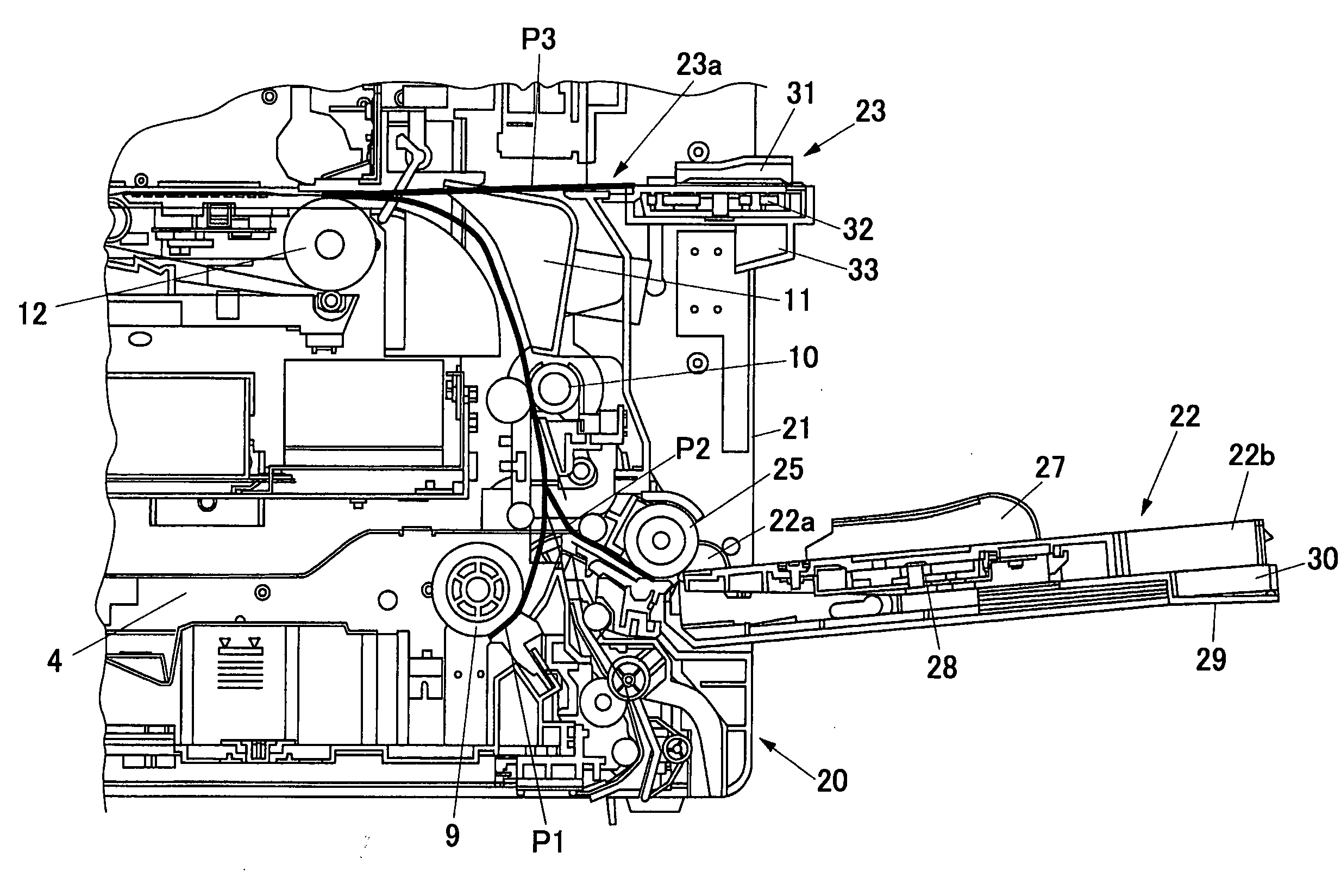
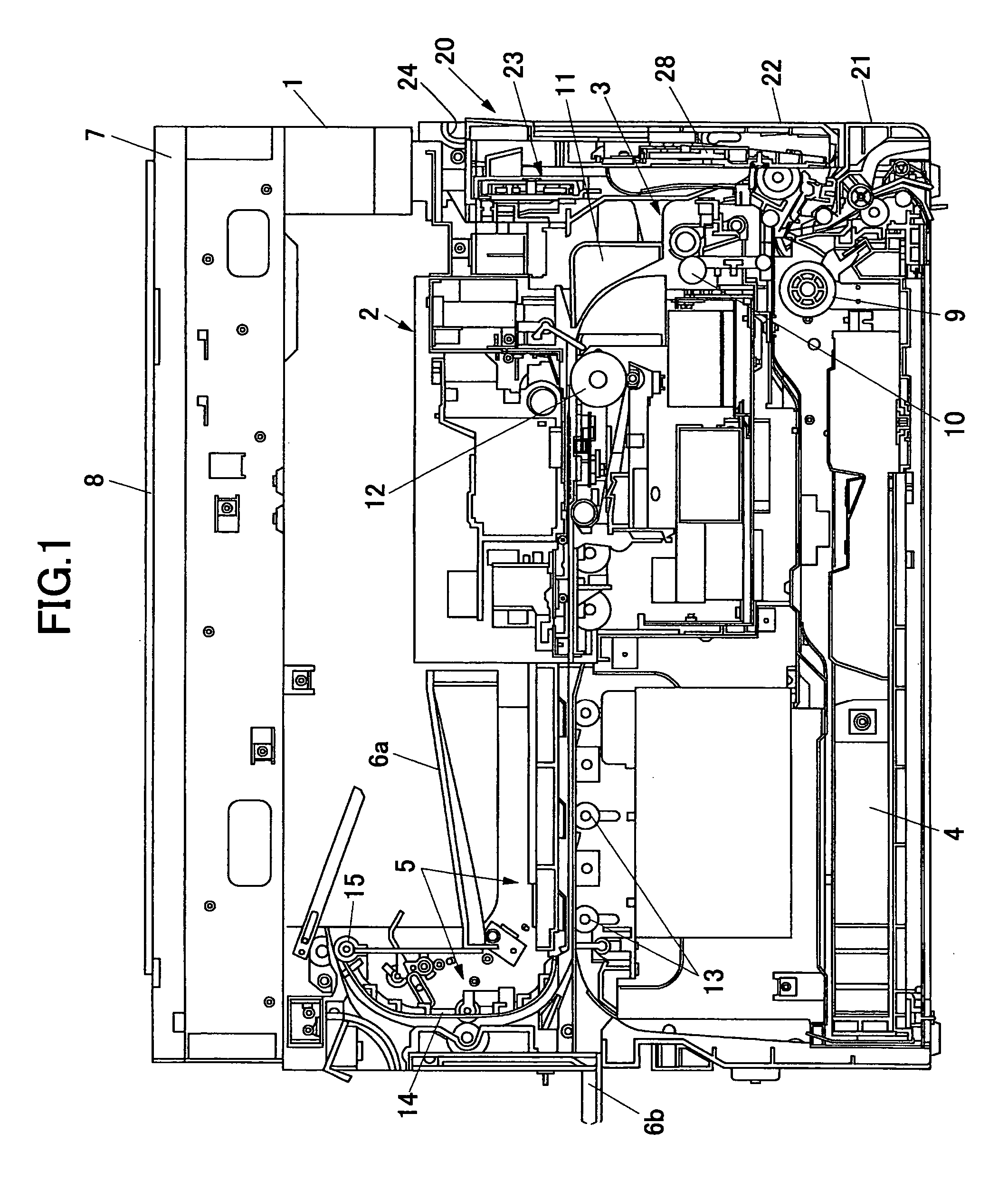
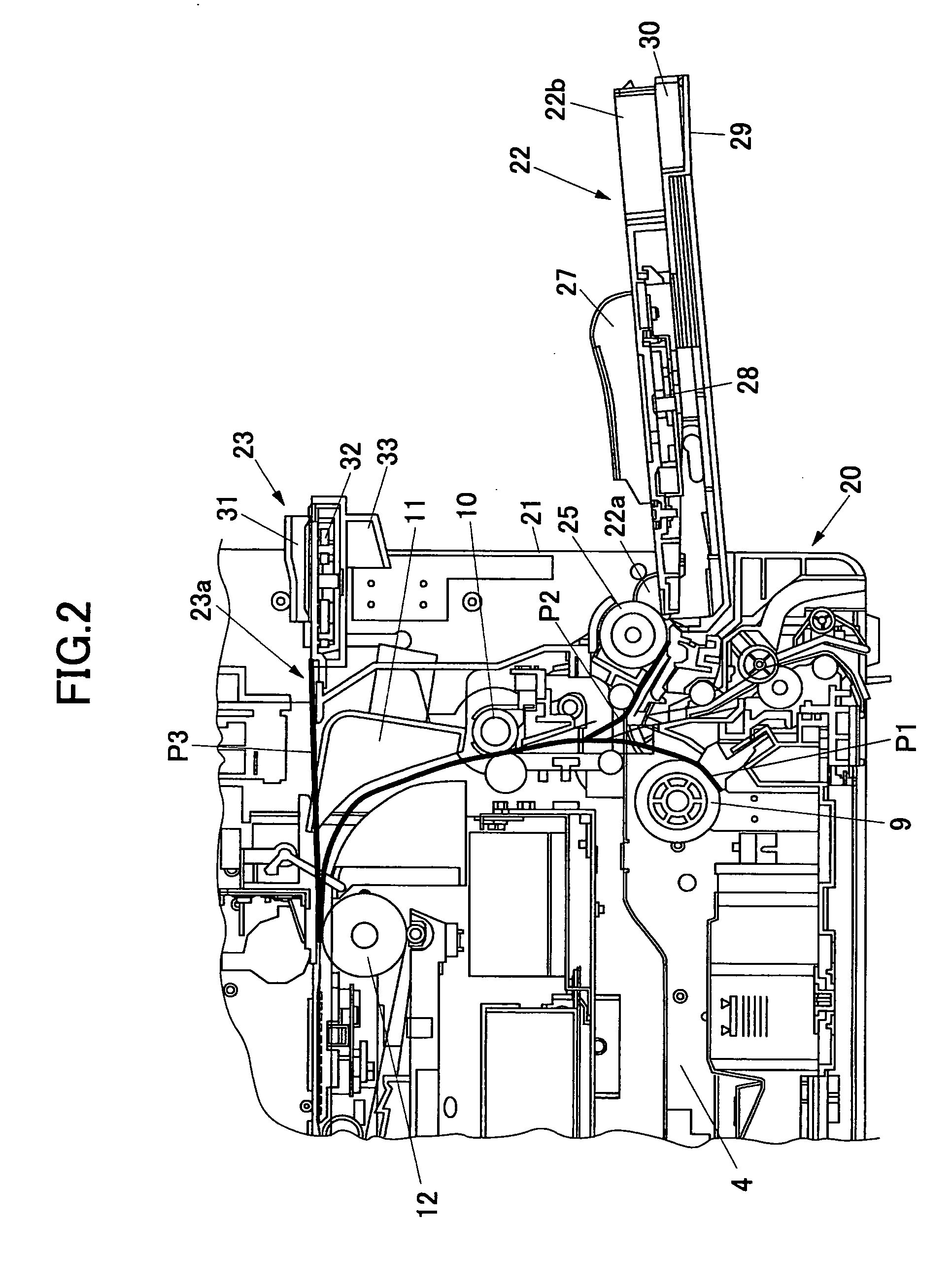
[0019]FIG. 1 is a schematic cross-sectional view of an image forming apparatus (such as a copier, a printer, or a facsimile machine) including a manual paper feeder 20 according to the embodiment of the present invention. FIG. 2 is an enlarged cross-sectional view of the manual paper feeder 20 and its vicinity. FIG. 3 is a perspective view of the manual paper feeder 20 and a right door 21 to which the manual paper feeder 20 is provided. The image forming apparatus of this embodiment includes an image forming part 2 and a conveyance part 3 in an apparatus main body 1. Based on a command from a scanner or a control unit (not graphically illustrated), recording media such as paper sheets are fed one by one from the uppermost one from a main body paper feed unit 4 provided at the bottom of the apparatus main body 1. Each fed paper sheet is conveyed in a position o...


PUM


Abstract

A paper feeder for feeding paper in an image forming apparatus is disclosed. The paper feeder includes multiple manual paper feed openings and multiple manual paper feed parts positioned corresponding to the manual paper feed openings. The manual paper feed openings and the manual paper feed parts are provided in the main body of the paper feeder.

Description

BACKGROUND OF THE INVENTION [0001] 1. Field of the Invention [0002] The present invention relates generally to paper feeders and more particularly to a paper feeder used for manual paper feed in image forming apparatuses such as copiers, printers, and facsimile machines. [0003] 2. Description of the Related Art [0004] Some image forming apparatuses such as copiers have an automatic paper feed unit and a manual paper feed unit including a manual paper feed tray provided to a manual paper feed opening. In the automatic paper feed unit, a stack of paper sheets is set in one or multiple paper feed cassettes disposed in the main body of the image forming apparatus (the apparatus main body), and the uppermost one of the paper sheets is fed out based on a command. The manual paper feed unit is used to form an image on a paper sheet of a type or size that is not set in the paper feed cassettes of the automatic paper feed unit. [0005] Some conventional image forming apparatuses employ a manu...

Claims


Application Information

Patent Timeline
17 Nov 2005
Publication
US20050253323A1
IPC
B65H1/04; B65H3/44; B65H11/00; B65H5/26
CPC
B65H1/04; B65H2407/21; B65H2405/332; B65H3/44
Inventors
FUJITA, AKIHIRO; NONAKA, MANABU