Apparatus and method for improving signal-to-noise ratio in a multi-carrier CDMA communication system

a communication system and multi-carrier technology, applied in multiplex communication, orthogonal multiplex, baseband system details, etc., can solve the problems of wasting scarce bandwidth, repeated transmission of m copies of the same signal, and averaged effect, so as to improve the detection and demodulation of digital data, reduce the required energy per chip, and improve the reception of overhead signals

Inactive Publication Date: 2005-12-01
SAMSUNG ELECTRONICS CO LTD
View PDF6 Cites 11 Cited by
  • Summary
  • Abstract
  • Description
  • Claims
  • Application Information

AI Technical Summary

Benefits of technology

[0012] The present invention improves the detection and demodulation of digital data in multi-carrier CDMA (MC-CDMA) communication systems and OFDM-CDMA communication systems. The present invention may be implemented in any system that employs frequency division duplexing (FDD) or time division duplexing (TDD). This present invention reduces the required energy per chip in processing multiple, reconstructed samples of the received signal. This allows a CDMA receiver to operate closer to the Shannon limit. The method is very useful for improved reception of overhead signals in systems employing smart antenna technology, where the transmission of overhead signals does not employ adaptive beam forming.

Problems solved by technology

However, this approach requires a large number of components and a large circuit area.
Additionally, the repeated transmission of M copies of the same signal is wasteful of scarce bandwidth.
However, the fact that each wireless terminal must transmit its signal over the entire spectrum leads to an averaged-down effect in the presence of deep fading and narrowband interference.
This is not ideally suited for the frequency domain signals that are present in MC-CDMA and OFDM-CDMA receivers.

Method used


Image

  • Apparatus and method for improving signal-to-noise ratio in a multi-carrier CDMA communication system
  • Apparatus and method for improving signal-to-noise ratio in a multi-carrier CDMA communication system
  • Apparatus and method for improving signal-to-noise ratio in a multi-carrier CDMA communication system

Examples


Embodiment Construction

[0028]FIGS. 1 through 5, discussed below, and the various embodiments used to describe the principles of the present invention in this patent document are by way of illustration only and should not be construed in any way to limit the scope of the invention. Those skilled in the art will understand that the principles of the present invention may be implemented in any suitably arranged wireless receiver.

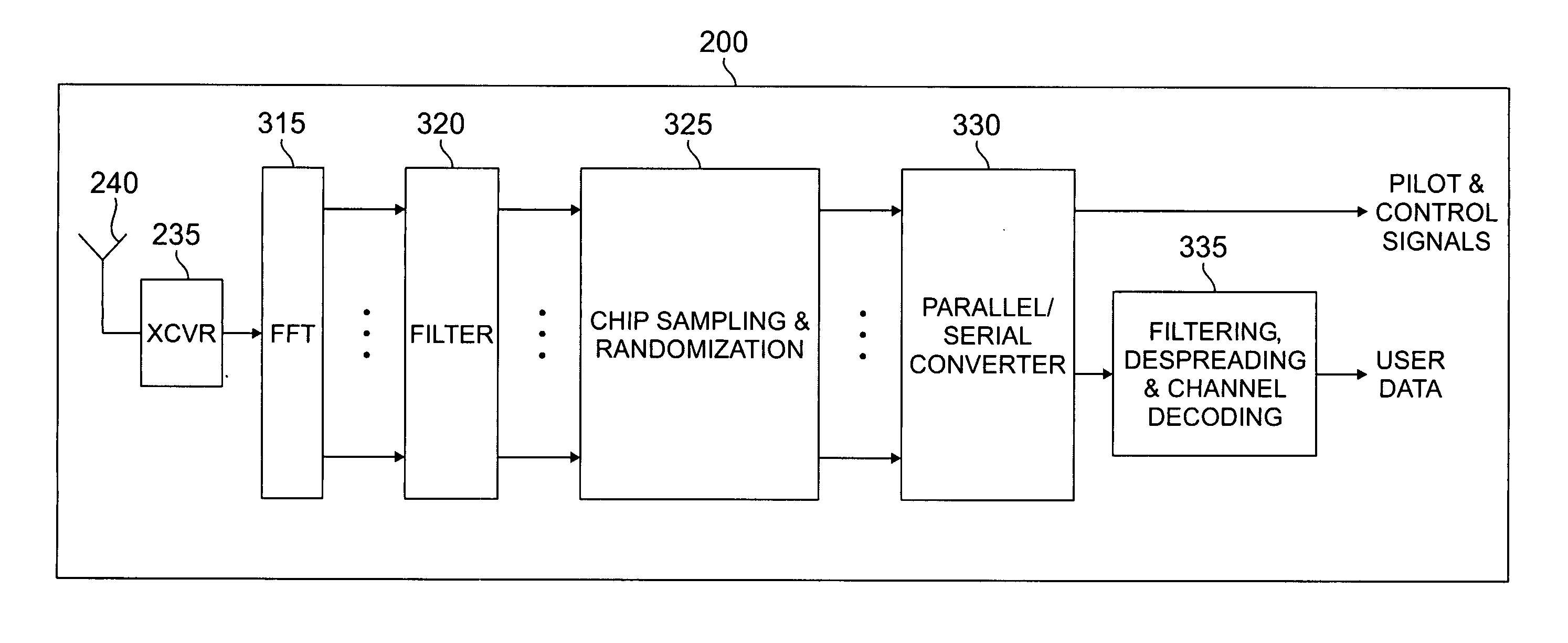
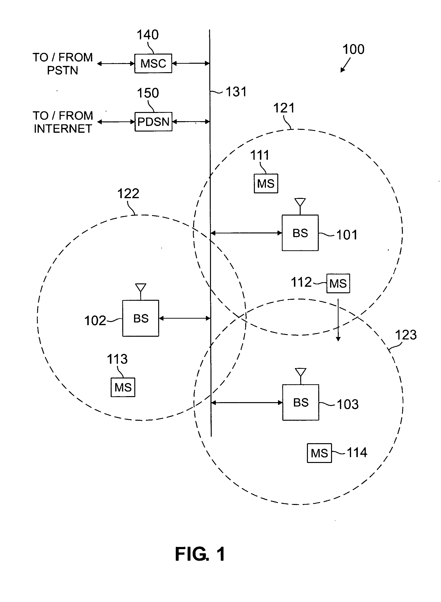
[0029]FIG. 1 illustrates exemplary wireless network 100, which implements wireless receivers according to the principles of the present invention. Wireless network 100 comprises a plurality of cell sites 121-123, each containing one of the base stations, BS 101, BS 102, or BS 103. According to the principles of the present invention, base stations 101-103 communicate with a plurality of mobile stations (MS) 111-114 using multi-carrier (MC) code division multiple access (CDMA) channels or orthogonal frequency division multiplexing (OFDM) CDMA channels. In an advantageous embodiment o...


PUM


Abstract

For use in a multi-carrier CDMA receiver, a noise reduction circuit for improving a signal-to-noise ratio of a multi-carrier signal corresponding to a predetermined sequence of chips. Each chip has a value of Logic 0 or Logic 1. The noise reduction circuit comprises a Fast Fourier Transform (FFT) circuit for receiving the multi-carrier signal and generating frequency-domain component signals. A sampling circuit generates a first sequence of samples of the frequency-domain component signals. A controller identifies samples in the first sample sequence corresponding to Logic 0 chips and identifies samples in the first sample sequence corresponding to Logic 1 chips. A randomizing circuit generates a second sample sequence by shifting positions within the first sample sequence of some of the identified samples corresponding to Logic 0 chips, or by shifting positions within the first sample sequence of some of the identified samples corresponding to Logic 1 chips.

Description

TECHNICAL FIELD OF THE INVENTION [0001] The present invention is directed, in general, to wireless communications devices and, more specifically, to an RF receiver having a lower signal-to-noise ratio. BACKGROUND OF THE INVENTION [0002] Wireless communications systems, including cellular phones, paging devices, personal communication services (PCS) systems, and wireless data networks, have become ubiquitous in society. Wireless service providers continually try to create new markets for wireless devices and to expand existing markets by making wireless devices and services cheaper and more reliable. The price of end-user wireless devices, such as cell phones, pagers, PCS systems, and wireless modems, has been driven down to the point where these devices are affordable to nearly everyone and the price of a wireless device is only a small part of the end-user's total cost. To continue to attract new customers, wireless service providers concentrate on reducing infrastructure costs and...

Claims


Application Information

Patent Timeline
Patent Type & Authority Applications(United States)
IPC IPC(8): H04B7/216H04B17/40H04J11/00H04L5/02H04L27/26
CPCH04L5/0021H04L5/0048H04L27/2647H04L25/0228H04L25/03299H04L25/022
Inventor CLEVELAND, JOSEPH R.
Owner SAMSUNG ELECTRONICS CO LTD
Why Eureka
Try Eureka