Data center evaluation using an air re-circulation index

a data center and air recirculation technology, applied in the direction of computer control, digital computer details, temperatue control, etc., can solve the problems of data center cooling, data center computer systems may only utilize around 30-50% of the maximum cooling capacity, and temperatures to exceed a predetermined temperature rang

Active Publication Date: 2005-12-01
HEWLETT-PACKARD ENTERPRISE DEV LP +1
View PDF3 Cites 139 Cited by
  • Summary
  • Abstract
  • Description
  • Claims
  • Application Information

AI Technical Summary

Benefits of technology

[0007] In a method for evaluating one or more components in a data center, inlet and outlet temperatures of one or more heat dissipating devices are detected. In addition, the temperatures of air supplied by one or more computer room air conditioning (CRAC) units are also detected. Indices of air re-circulation for the one or more heat dissipating devices are calculated based upon the detected inlet temperatures, outlet temperatures and supplied air temperatures. The indices of air re-circulation are determined at various flow field settings of air delivered to the one or more heat dissipating devices and the one or more components are evaluated based upon changes in the indices of air re-circulation for the one or more heat dissipating devices at the various flow field settings.

Problems solved by technology

As such, the cooling of data centers presents problems in addition to those faced with the cooling of the racks.
However, the computer systems in the data center may only utilize around 30-50% of the maximum cooling capacity.
In this respect, conventional cooling systems often attempt to cool components that may not be operating at a level which may cause their temperatures to exceed a predetermined temperature range.
Consequently, many conventional cooling systems often incur greater amounts of operating expenses than may be necessary to sufficiently cool the heat generating components contained in the racks of data centers.
Consequently, conventional data centers oftentimes have infrastructures that are not efficiently designed for varying heat loads and airflows.
In this regard, the energy required to cool the components contained in the racks is usually consumed in inefficient manners as additional energy is required to compensate for the non-optimized data center layouts.

Method used


Image

  • Data center evaluation using an air re-circulation index
  • Data center evaluation using an air re-circulation index
  • Data center evaluation using an air re-circulation index

Examples


Embodiment Construction

[0017] For simplicity and illustrative purposes, the present invention is described by referring mainly to an exemplary embodiment thereof. In the following description, numerous specific details are set forth in order to provide a thorough understanding of the present invention. It will be apparent however, to one of ordinary skill in the art, that the present invention may be practiced without limitation to these specific details. In other instances, well known methods and structures have not been described in detail so as not to unnecessarily obscure the present invention.

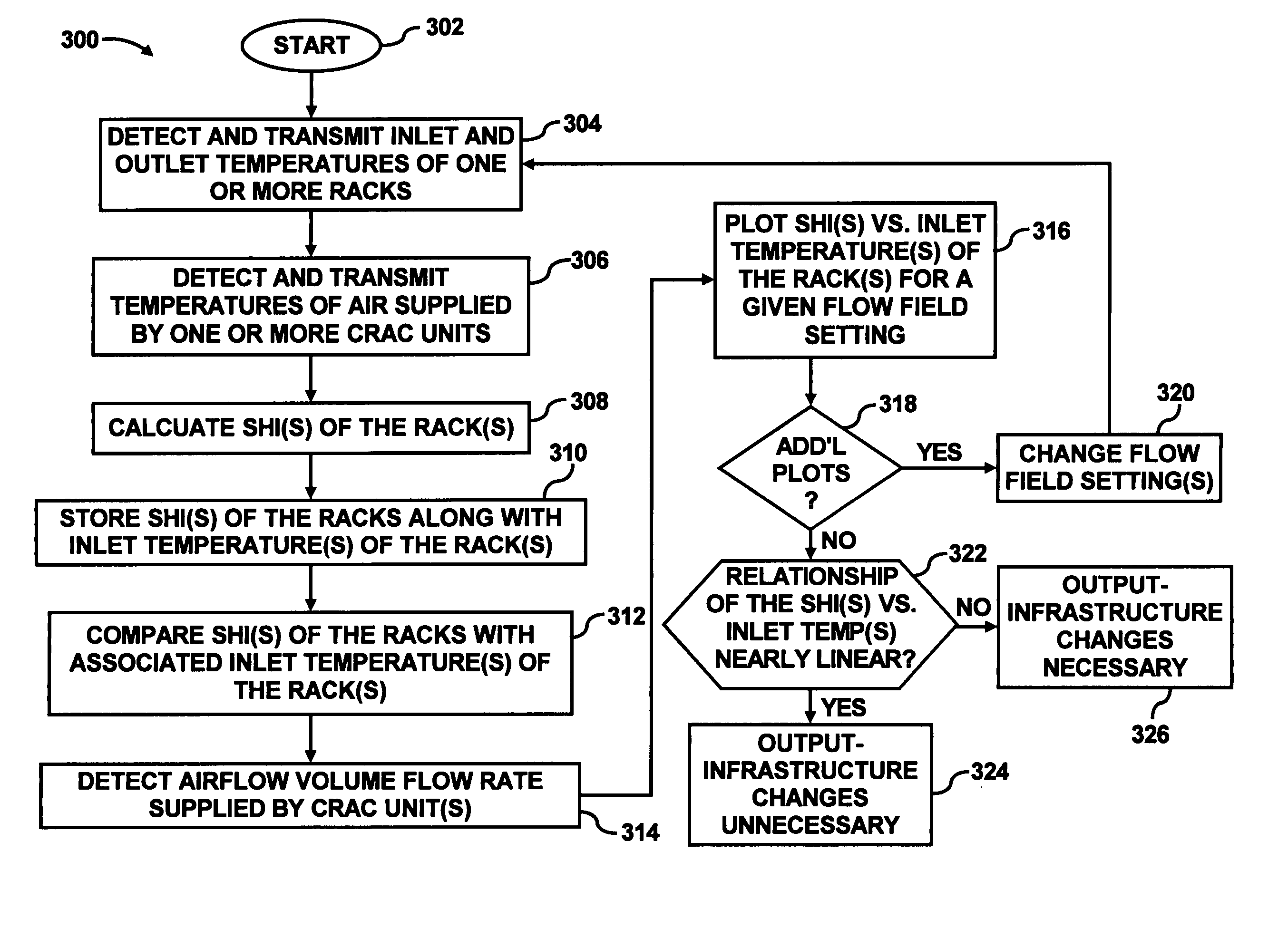
[0018] An index of air re-circulation is employed for various purposes in at least one of the layout design, deployment, and evaluation of data centers. In one respect, various air re-circulation indices are calculated for various flow field settings. The flow field settings may include, for instance, the volume flow rates of one or more CRAC units, the airflow characteristics through one or more vent tiles, th...


PUM


Abstract

In a method for evaluating one or more components in a data center, inlet and outlet temperatures of one or more heat dissipating devices are detected. In addition, the temperatures of air supplied by one or more computer room air conditioning (CRAC) units are also detected. Indices of air re-circulation for the one or more heat dissipating devices are calculated based upon the detected inlet temperatures, outlet temperatures and supplied air temperatures. The indices of air re-circulation are determined at various flow field settings of air delivered to the one or more heat dissipating devices and the one or more components are evaluated based upon changes in the indices of air re-circulation for the one or more heat dissipating devices at the various flow field settings.

Description

BACKGROUND OF THE INVENTION [0001] A data center may be defined as a location, for instance, a room, that houses computer systems arranged in a number of racks. A standard rack, for example, an electronics cabinet, is defined as an Electronics Industry Association (EIA) enclosure, 78 in. (2 meters) high, 24 in. (0.61 meter) wide and 30 in. (0.76 meter) deep. These racks are configured to house a number of computer systems, about forty (40) systems, with future configurations of racks being designed to accommodate 200 or more systems. The computer systems typically include a number of printed circuit boards (PCBs), mass storage devices, power supplies, processors, micro-controllers, and semi-conductor devices, that dissipate relatively significant amounts of heat during their operation. For example, a typical computer system comprising multiple microprocessors dissipates approximately 250 W of power. Thus, a rack containing forty (40) computer systems of this type dissipates approxim...

Claims


Application Information

Patent Timeline
Patent Type & Authority Applications(United States)
IPC IPC(8): G05B13/00G05B15/00G05B21/00G05D23/00G05D23/19G06F1/20H05K7/20
CPCF24F11/0012G05D23/1931H05K7/20836H05K7/20745G06F1/206F24F11/30F24F2110/10
Inventor SHARMA, RATNESH K.BASH, CULLEN E.PATEL, CHANDRAKANT D.
Owner HEWLETT-PACKARD ENTERPRISE DEV LP
Why Eureka
Try Eureka