
Mini fan to be fixed in a recess of a wall
a technology of fan and recess, which is applied in the direction of motors, electrical equipment, electrical apparatus, etc., can solve the problems of more expensive mounting types and other problems
- Summary
- Abstract
- Description
- Claims
- Application Information
AI Technical Summary
Benefits of technology
Problems solved by technology
Method used
Image

Examples
first embodiment
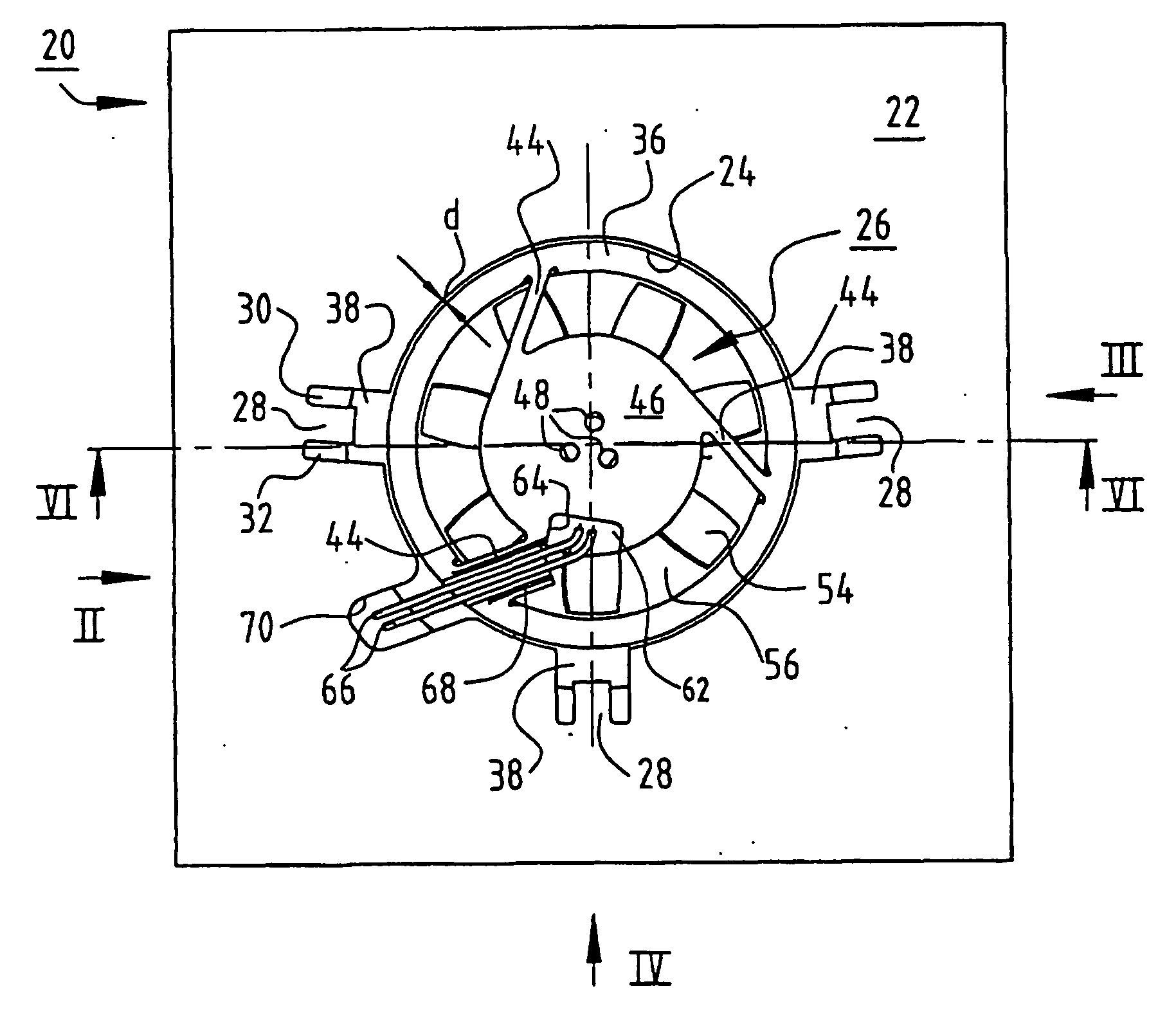
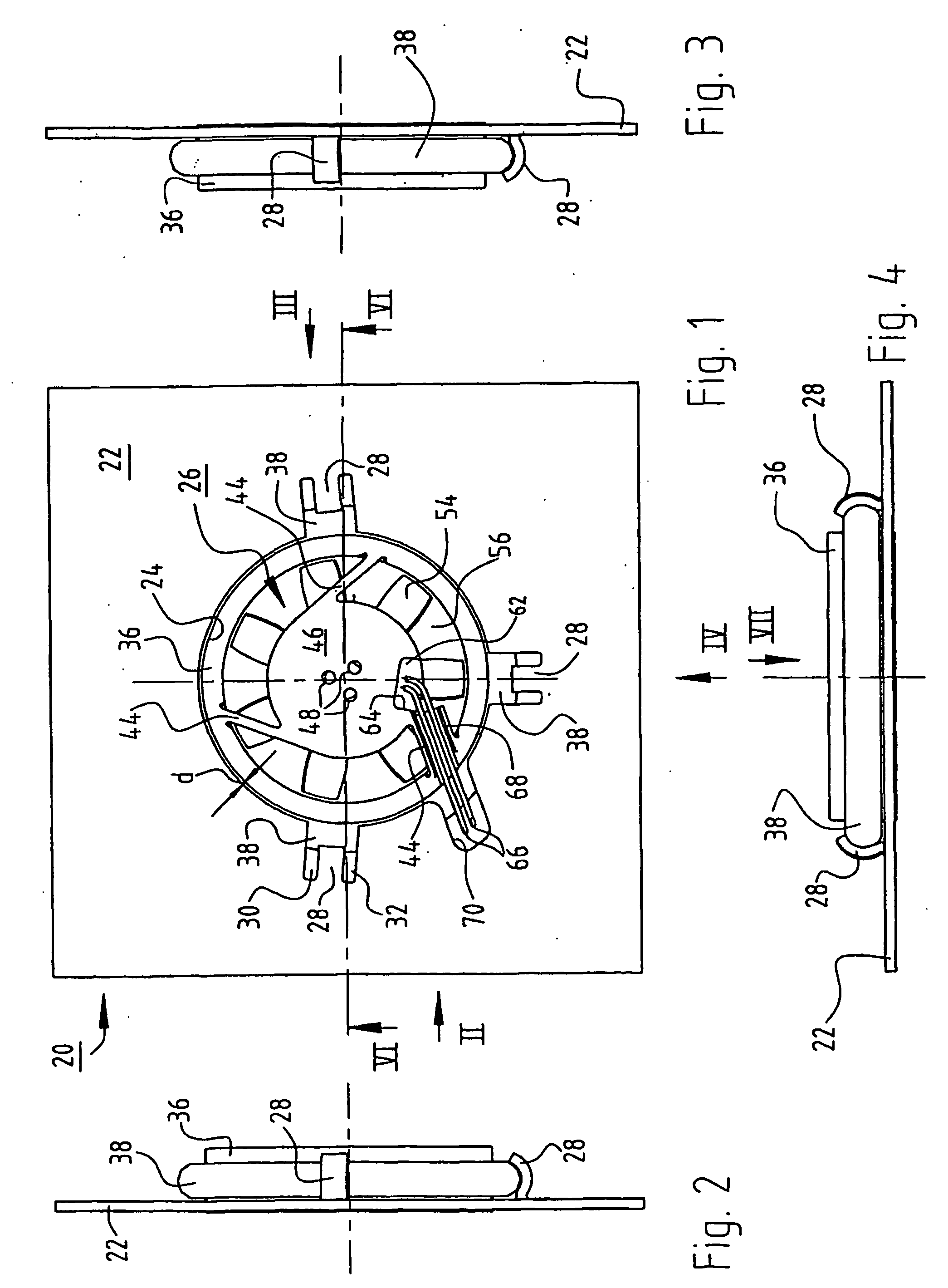
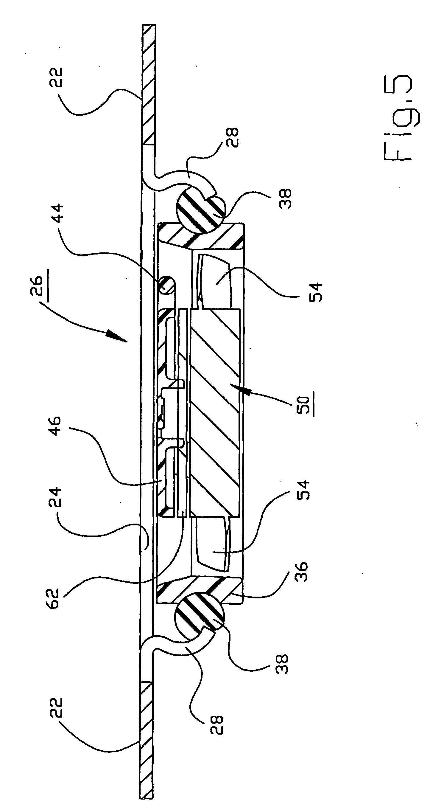
[0026] Implemented at the edge of recess 24 are a plurality of retaining members 28 whose shape is best inferred from FIGS. 1 and 5. In the context of the first embodiment according to FIGS. 1 through 8, retaining members 28 deflect substantially in the radial direction. They are each constituted by two parallel stamped cuts 30, 32 that extend approximately radially outward with respect to recess 24, and they are bent in the manner depicted in FIGS. 5 and 6 to form resilient tabs or retaining prongs that can deflect approximately radially outward upon installation and removal. In the region of their roots, retaining members 28 are preferably provided with a bead 34 for stiffening (see FIG. 7).
[0027] As is apparent in particular from FIG. 6, fan 26 has for air guidance an outer housing part 36 which is substantially round in this embodiment but could also have a different shape, and on which is mounted in suitable fashion an annular elastomeric part, here in the form of an O-ring 38 ...
second embodiment
[0034]FIGS. 9 through 15 show a second exemplifying embodiment of the invention. As compared with the embodiment according to FIGS. 1 through 8, the second embodiment is more inexpensive to manufacture, and it makes possible subsequent removal of the fan only with exertion of a great deal of force. In addition, a strain-relief element for the connecting conductors is provided in this variant.
[0035] Commonalities exist between the first and the second embodiment. Identical or identically functioning parts are therefore labeled in FIGS. 9 through 15 with reference characters that are incremented by 100 as compared with FIGS. 1 through 8, e.g. 122 instead of 22. These parts are usually not described again.
[0036] Arrangement 120 has a wall 122 in which is located a recess 124 into which a fan 126 protrudes with a housing portion127. Recess 124 and housing portion 127 are complementary in shape, e.g. substantially round as depicted.
[0037] A plurality of retaining members or retaining p...
PUM
 Abstract
Description
Claims
Application Information