First person acoustic environment system and method

Inactive Publication Date: 2005-12-22
SOUND DESIGN TECH
View PDF10 Cites 16 Cited by
  • Summary
  • Abstract
  • Description
  • Claims
  • Application Information

AI Technical Summary

Benefits of technology

[0004] In-ear monitors often plug the ear completely to allow an external mix of the acoustical environment to be provided to a user while minimizing outside interference. This results in a clean mix of the separate instruments and vocals that ar

Problems solved by technology

This results in a clean mix of the separate instruments and vocals that are being played within a musical setting, but limits the wearer's ability to control th

Method used


Image

  • First person acoustic environment system and method
  • First person acoustic environment system and method
  • First person acoustic environment system and method

Examples


Embodiment Construction

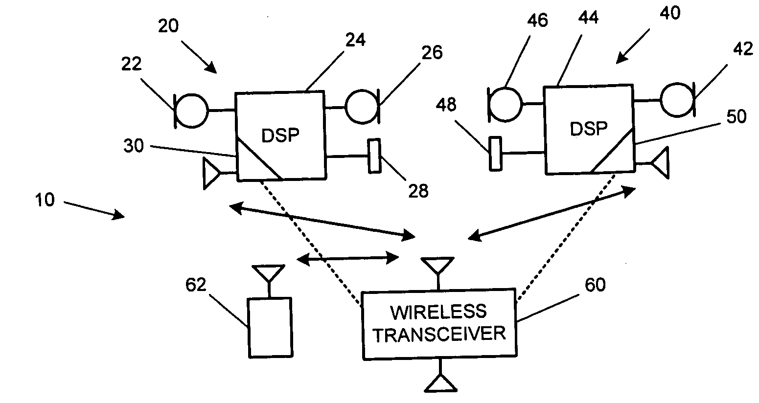
[0018]FIG. 1 is a block diagram of an in-ear monitoring component package 10 for a wearer, such as a musician or entertainment performer. The component package 10 comprises first and second in-ear monitors 20 and 40 and a wireless transceiver 60 that is associated with the wearer. The first in-ear assembly 20 comprises an outside microphone 22, a DSP device 24, an occlusion microphone 26, a transducer 28, and a communication subsystem 30. The outside microphone 22 receives sounds from the ambient acoustic environment external to the wearer and converts the sounds into corresponding electrical signals that are, in turn, provided to the DSP device 24.

[0019] The occlusion effect is the amplification of the wearer's own biologic sounds and voice within the ear canal. The occlusion microphone 26 is thus inside the ear canal to receive this unwanted signal created by the occlusion effect. The occlusion microphone 26 receives sounds from the wearer's inner ear and converts the sounds into...


PUM


Abstract

An in-ear monitoring system transmits right- and left-channel audio data for one or more in-ear playback devices to create a first person acoustic environment for one or more third persons.

Description

REFERENCE TO RELATED APPLICATIONS [0001] This patent application claims the benefit of priority to U.S. Provisional Application Ser. No. 60 / 581,668, entitled “In Ear Monitoring System And Method,” filed on Jun. 22, 2004, the entire disclosure of which is incorporated herein by reference. [0002] This patent application is related to U.S. patent application Ser. No. 11 / ______, entitled “In-Ear Monitoring System And Method With Bidirectional Channel,” filed on Jun. 22, 2005, and U.S. patent application Ser. No. 11 / ______, entitled “In-Ear Monitoring System And Method,” filed on filed on Jun. 22, 2005, the disclosures of which are incorporated herein by reference.BACKGROUND AND SUMMARY [0003] This disclosure relates in general to hearing instruments, and in particular relates to in-ear monitor (IEM) systems and methods. [0004] In-ear monitors often plug the ear completely to allow an external mix of the acoustical environment to be provided to a user while minimizing outside interferenc...

Claims


Application Information

Patent Timeline
IPC IPC(8): H04R1/10H04R3/00H04R5/033H04R5/04H04R25/00
CPCH04H20/61H04R1/083H04R1/1016H04R5/033H04R25/00H04R25/30H04R2460/05H04R25/453H04R25/505H04R25/554H04R2225/55H04R2420/01H04R2420/07H04R25/407H04R27/00
Inventor ARMSTRONG, STEPHEN W.
Owner SOUND DESIGN TECH
Why Eureka
Try Eureka