Eureka AIR delivers breakthrough ideas for toughest innovation challenges, trusted by R&D personnel around the world.

Adaptive vehicle communication controlled lighting system

a communication control and vehicle technology, applied in the field of vehicle headlight systems, can solve the problems of adding additional cost to the vehicle, affecting the operation of the vehicle, and reducing the efficiency of the vehicle, so as to minimize the complexity of the system, minimize the impact of manufacturing time and costs, and maximize the illumination output

Active Publication Date: 2009-06-02
FORD GLOBAL TECH LLC
View PDF24 Cites 215 Cited by
  • Summary
  • Abstract
  • Description
  • Claims
  • Application Information

AI Technical Summary

Benefits of technology

The present invention is a vehicle safety system that includes a light source and a beam-forming assembly. An object detection sensor detects objects and sends a signal to a controller, which adjusts the illumination output of the system accordingly. The invention has several advantages, including an adaptive headlight system that minimizes glare and interference, a shared safety system between headlights and other safety functions, and versatility in detecting and communicating with objects. Overall, the invention simplifies safety system operations and reduces costs.

Problems solved by technology

The relief is limited and the reflections can still be annoying to vehicle occupants.
The electrochromatic mirrors provide limited use, but yet add additional cost to a vehicle.
All of the above-mentioned vehicle headlight systems have a common drawback of being limited to very few headlight beam illumination patterns or include numerous mechanical elements to steer or otherwise modify the headlight beam illumination pattern.
Additionally, the above vehicle headlight systems are limited in their ability to maximize illumination from a host vehicle while minimizing glare to nearby vehicles.

Method used


Image

  • Adaptive vehicle communication controlled lighting system
  • Adaptive vehicle communication controlled lighting system
  • Adaptive vehicle communication controlled lighting system

Examples


Embodiment Construction

[0022]In the drawing figures discussed as follows, the same reference numerals will generally be used to refer to the same components. The present invention may be adapted and applied to various sensing systems including, for example, headlight systems, collision warning systems, collision avoidance systems, parking-aid systems, reversing-aid systems, passive countermeasure systems, adaptive cruise control systems, lane departure systems, lane-keeping systems, windshield clearing systems, or other systems known in the art.

[0023]In the following description, various operating parameters and components are described for multiple constructed embodiments. These specific parameters and components are included as examples and are not meant to be limiting.

[0024]Also, the term “object” may refer to any animate or inanimate object. An object may be a vehicle, illumination from a headlight, a light signal, a pedestrian, a lane marker, a road sign, a roadway lane designating line, a vehicle oc...


PUM


Abstract

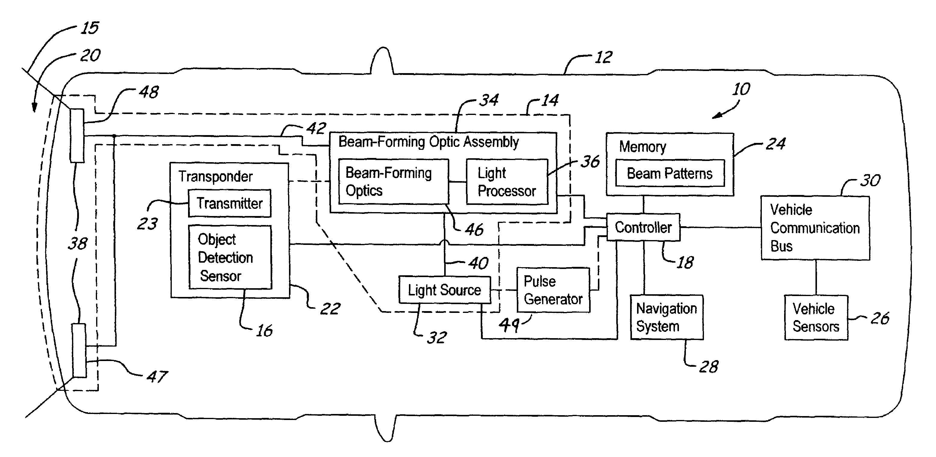
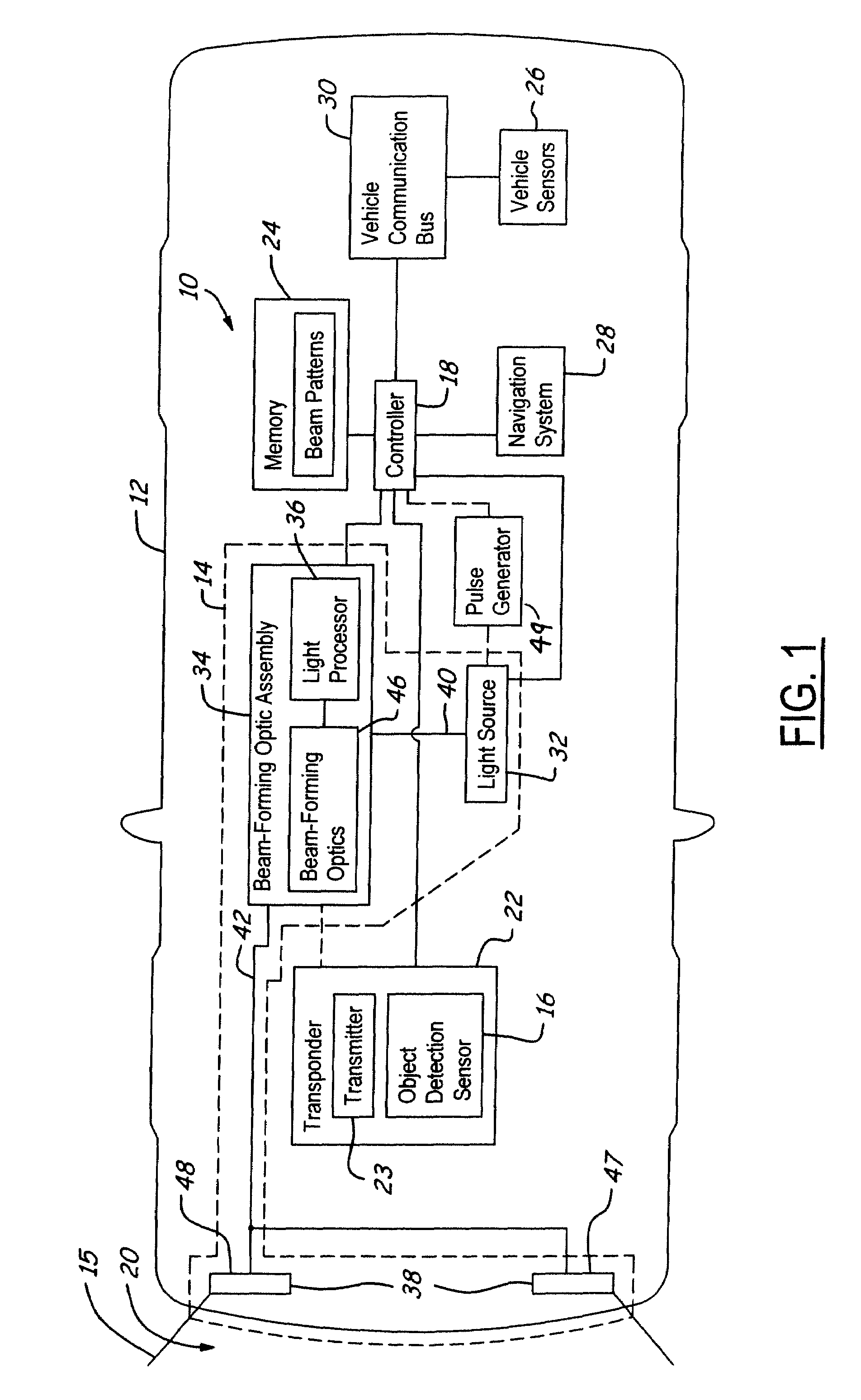
A vehicle safety system (10) includes a light source (32). A beam-forming assembly (34) is optically coupled to the light source (32). An object detection sensor (16) detects an object and generates an object detection signal. A controller (18) is coupled to the beam-forming assembly (34) and the object detection sensor (16). The controller (18) adjusts illumination output of the vehicle safety system (10) in response to the object detection signal.

Description

CROSS REFERENCE TO RELATED APPLICATIONS[0001]The present application claims priority to U.S. Provisional Application Ser. No. 60 / 432,973, entitled “TRANSPONDER CONTROLLED ADAPTIVE LIGHTING FOR ENHANCED VISABILTY AND SAFETY,” filed on Dec. 13, 2002, the disclosure of which is incorporated by reference herein.BACKGROUND OF INVENTION[0002]The present invention relates to vehicle headlight systems. More particularly, the present invention relates to an adaptive vehicle lighting system for improved visibility and roadway illumination.[0003]It is desired by vehicle manufacturers to improve roadway illumination of a host vehicle without negatively affecting visibility of other nearby or on-coming vehicles. Improved roadway illumination can improve drivability and safety aspects associated with operation of the host vehicle, especially in low-illumination or low visibility conditions. Some low visibility conditions are, for example, driving at night, driving through a tunnel, and driving in...

Claims


Application Information

Patent Timeline
Patent Type & Authority Patents(United States)
IPC IPC(8): B60Q1/14B60Q1/26B60Q1/08G01S13/931
CPCB60Q1/085G01S13/931B60Q2300/056B60Q2300/112B60Q2300/122B60Q2300/132B60Q2300/134B60Q2300/136B60Q2300/142B60Q2300/312B60Q2300/322B60Q2300/324B60Q2300/41B60Q2300/42B60Q2300/45G01S2013/9321G01S2013/935G01S2013/9364G01S2013/9367G01S2013/9325G01S2013/9339G01S2013/936G01S2013/9353G01S2013/9357G01S2013/9319G01S2013/9322G01S2013/9316G01S2013/9329G01S2013/9324G01S2013/9323G01S2013/932
Inventor SALMEEN, IRVING TOIVOMILLER, RONALD HUGHDIMEO, DAVID M.STRUMOLO, GARY STEVENDASSANAYAKE, MAHENDRA SOMASARAALLES, SHERAN ANTHONYWAGNER, DAVID ANTHONY
Owner FORD GLOBAL TECH LLC
Why Eureka
Eureka Blog
Learn More