Gas turbine inlet conditioning system and method

a technology of gas turbines and inlet conditioning systems, which is applied in the direction of steam engine plants, hot gas positive displacement engine plants, machines/engines, etc., can solve the problems of reducing the efficiency of the compressor, increasing the limit, and achieving maximum output and efficiency, so as to maximize power output and efficiency

a technology of gas turbines and inlet conditioning systems, which is applied in the direction of steam engine plants, hot gas positive displacement engine plants, machines/engines, etc., can solve the problems of reducing the efficiency of the compressor, increasing the limit, and achieving maximum output and efficiency, so as to maximize power output and efficiency

US20070240400A1Active Publication Date: 2007-10-18GENERAL ELECTRIC CO

Image

  • Gas turbine inlet conditioning system and method
  • Gas turbine inlet conditioning system and method
  • Gas turbine inlet conditioning system and method

Examples


Embodiment Construction

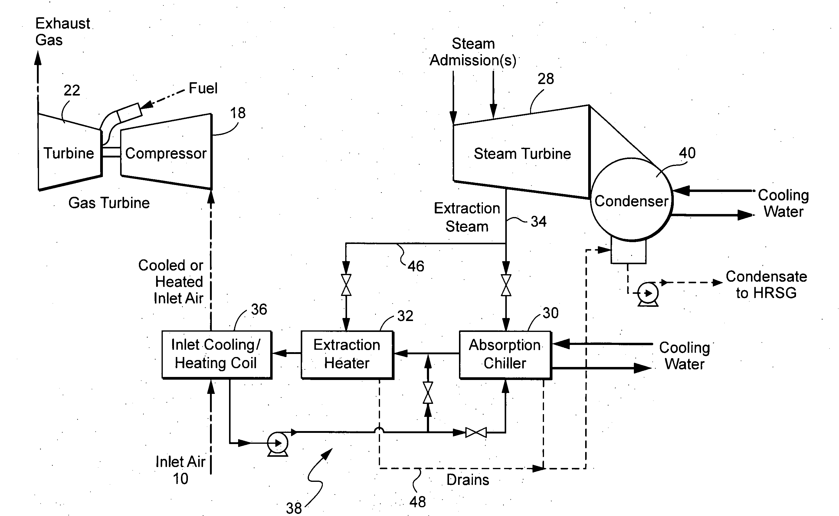
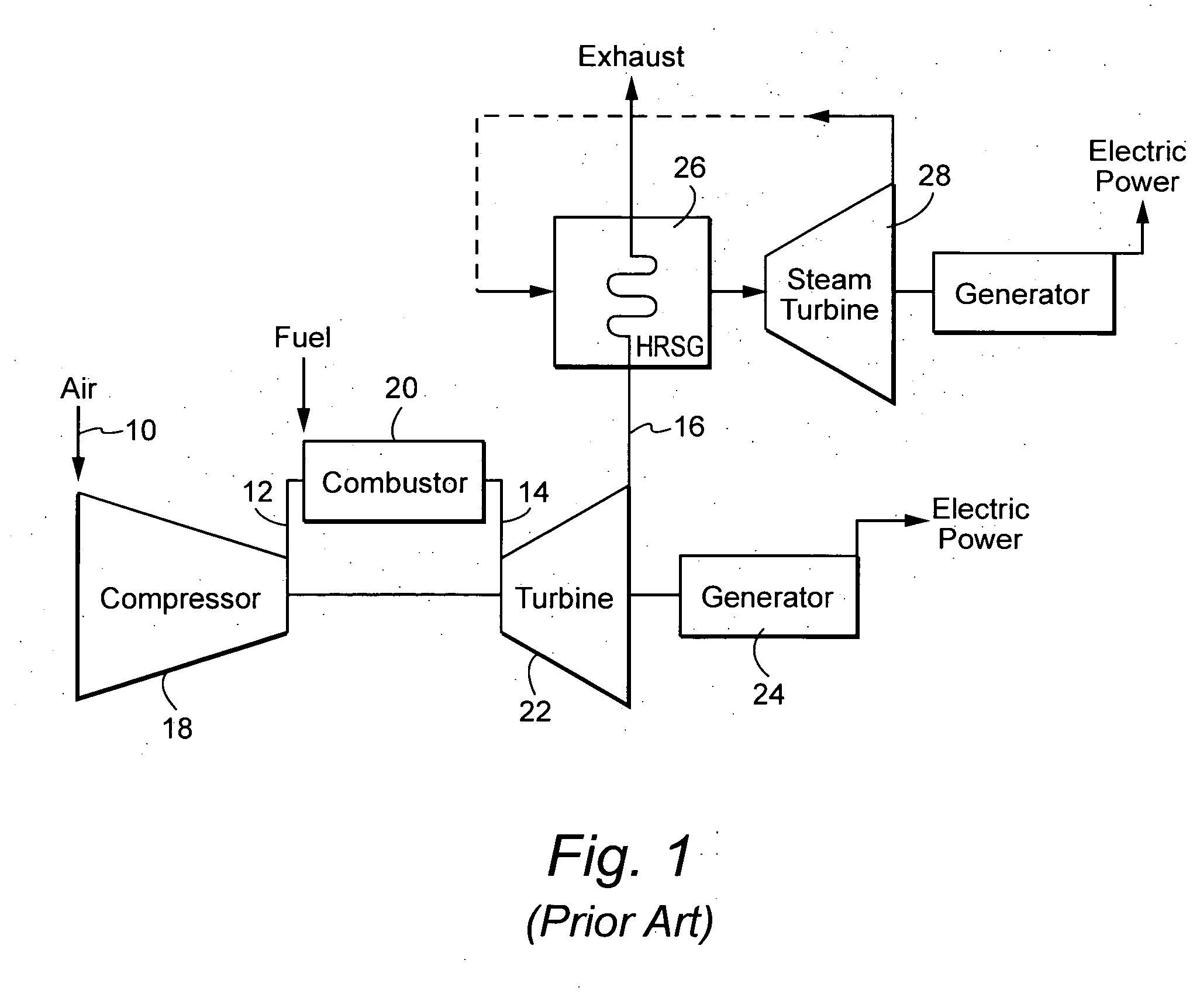
[0019] By way of background and with reference to the schematic illustration of FIG. 1, a typical combined cycle gas turbine includes, in serial-flow relationship, an intake or inlet for air 10, a compressor 18, a combustor 20, a turbine 22, a heat recovery steam generator (HRSG) 26 and its associated steam turbine 28. Thus, inlet air 10 enters the axial flow compressor 18 at ambient conditions. Ambient conditions vary from one location to another and day to day. Therefore, for comparative purposes standard conditions are used by the gas turbine industry. Those standard conditions are 59° F. (15° C.), 14.696 psia (1.013 bar), and 60% relative humidity. The standard conditions were established by the International Standards Organization (“ISO”) and are generally referred to as ISO conditions.

[0020] The compressed air 12 enters the combustion system 20 where fuel is injected and combustion occurs. The combustion mixture 14 leaves the combustion system and enters the turbine 22. In th...


PUM


Abstract

A system capable of both increasing warm day output and maintaining compressor operating margin across the ambient and load range of a gas turbine combined cycle installation. The proposed solution takes advantage of the fact that both goals can be satisfied by manipulation of compressor inlet air temperature. Specifically, the system is designed to heat inlet air as may be required to maintain safe compressor operating margin at low ambient air temperatures or when burning dilute fuels. In the alternative, the system is designed to cool inlet air on warm days.

Description

BACKGROUND OF THE INVENTION [0001] The invention relates to a system and method for heating and cooling compressor inlet air supplied to a gas turbine for the purpose of maximizing power output and efficiency across the load and ambient range. [0002] The combined cycle power plant in its simplest form is comprised of a gas turbine, a steam turbine, a generator, and a heat recovery steam generator (HRSG), with the gas turbine and steam turbine coupled to the single generator, in tandem on a single shaft. Multi-shaft arrangements having one or more gas turbine generators and a common steam turbine generator have been utilized. The thermal efficiency of combined cycle power plants is determined by the performance of the gas turbine in combination with its heat recovery bottoming cycle. [0003] Gas turbines have two characteristics that can become obstacles to achieving maximum output and efficiency across the operating range. [0004] First, gas turbines are constant volume flow machines....

Claims


Application Information

Patent Timeline
18 Oct 2007
Publication
US20070240400A1
IPC
F02C6/00
CPC
F01K23/101; Y02E20/16; F02C7/141; F02C7/08
Inventors
SMITH, RAUB WARFIELD; GULEN, SEYFETTIN CAN