Recuperated gas turbine engine system and method employing catalytic combustion

a gas turbine engine and catalytic combustion technology, which is applied in the ignition of turbine/propulsion engines, combustion control, combustion types, etc., can solve the problems of increasing the cost of the combustor, not being able to achieve less than one part per million, and not being able to achieve catalytic combustion, catalytic combustion, or catalytic combustion. or catalytic combustion. the effect of low level

Inactive Publication Date: 2006-03-07
MES INT INC
View PDF24 Cites 216 Cited by
  • Summary
  • Abstract
  • Description
  • Claims
  • Application Information

AI Technical Summary

Benefits of technology

[0007]In accordance with a method aspect of the invention, a method for operating a gas turbine engine comprises steps of compressing air in a compressor, mixing fuel with compressed air from the compressor to produce an air-fuel mixture, burning the air-fuel mixture in a catalytic combustor to produce hot combustion gases, expanding the combustion gases in a turbine to produce mechanical power and using the mechanical power to drive the compressor, and passing exhaust gases from the turbine through a recuperator in which the air-fuel mixture is pre-heated by heat exchange with the exhaust gases. The method includes the further step of directing a portion of exhaust gases from the turbine into the compressor. The fuel is also passed through the compressor along with the air and the portion of exhaust gases. The recirculation of the exhaust gas raises the inlet temperature to the combustor above what it would be without the exhaust gas recirculation. Ultimately what enters the combustor is a mixture of the air, fuel, and exhaust gases optimized to meet power output, maximize efficiency, and minimize air pollution
[0009]In accordance with the invention, the flow rate of the exhaust gases directed into the compressor is controlled in response to one or more parameters associated with the engine, at least one of which is the fuel / air ratio. For instance, the controlling step can comprise controlling the flow rate in response to a measured combustor inlet temperature so as to maintain the combustor inlet temperature higher than a predetermined minimum temperature necessary for proper operation of the catalytic combustor at that fuel / air ratio. In this manner, the flow rate of the exhausts gases into the compressor can be optimized to compensate for changes in ambient temperature and / or relative engine load.
[0010]The portion of exhaust gases directed into the compressor can be separated from the remainder of the exhaust gases at a point downstream of the recuperator. In this case, the recirculated exhaust gases will be reduced in temperature by their passage through the recuperator. Alternatively, the portion of exhaust gases directed into the compressor can be separated from the remainder of the exhaust gases at a point upstream of the recuperator such that the recirculated exhaust gases bypass the recuperator. In such an arrangement, the temperature of the recirculated exhaust gases fed to the compressor will be higher and therefore the recirculated exhaust gas flow rate can be lower than in the previously described arrangement.

Problems solved by technology

Using catalytic oxidation, NOx levels less than one part per million can be achieved under optimum catalytic oxidation conditions; such low levels in general cannot be achieved with conventional non-catalytic combustors, catalytic combustion, or cata-thermal combustion.
In addition, catalytic oxidation has the disadvantage that the physical reaction surface which must be supplied for complete oxidation of the hydrocarbon fuel increases exponentially with decreasing combustor inlet temperatures, which greatly increases the cost of the combustor and complicates the overall design.
The need for a relatively high combustor inlet temperature is one of the chief reasons why catalytic combustion in general, and catalytic oxidation in particular, has not achieved widespread use in gas turbine engine systems.
More specifically, such high combustor inlet temperatures generally cannot be achieved in gas turbines operating with compressor pressure ratios less than about 40 unless a recuperated cycle is employed.
However, there are often other operating conditions that will be encountered at which the minimum required combustor inlet temperature still cannot be achieved even with recuperation.
For instance, when recuperation is applied in small gas turbines, material temperature limitations in the recuperator can limit the maximum air or air-fuel mixture temperature.
This in turn allows the elimination of a fuel gas compressor, which is very costly particularly for small gas turbines.
Furthermore, the fuel gas compressor detracts from the reliability and availability of the engine, since it must operate in order for the engine to operate, and adds to the cost of maintenance because of oil, filters, mechanical or electrical wear out, and the like.

Method used


Image

  • Recuperated gas turbine engine system and method employing catalytic combustion
  • Recuperated gas turbine engine system and method employing catalytic combustion
  • Recuperated gas turbine engine system and method employing catalytic combustion

Examples


first embodiment

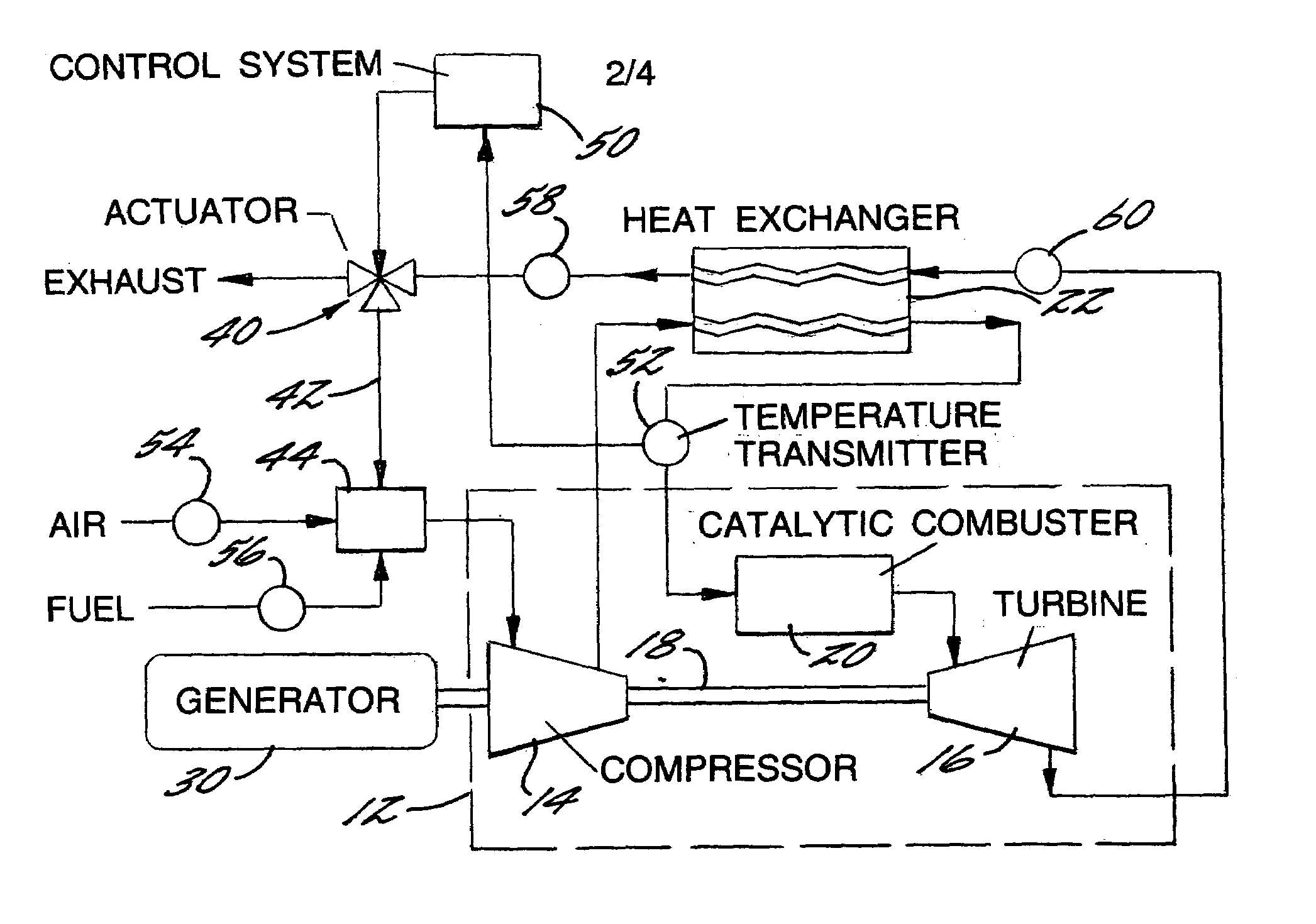
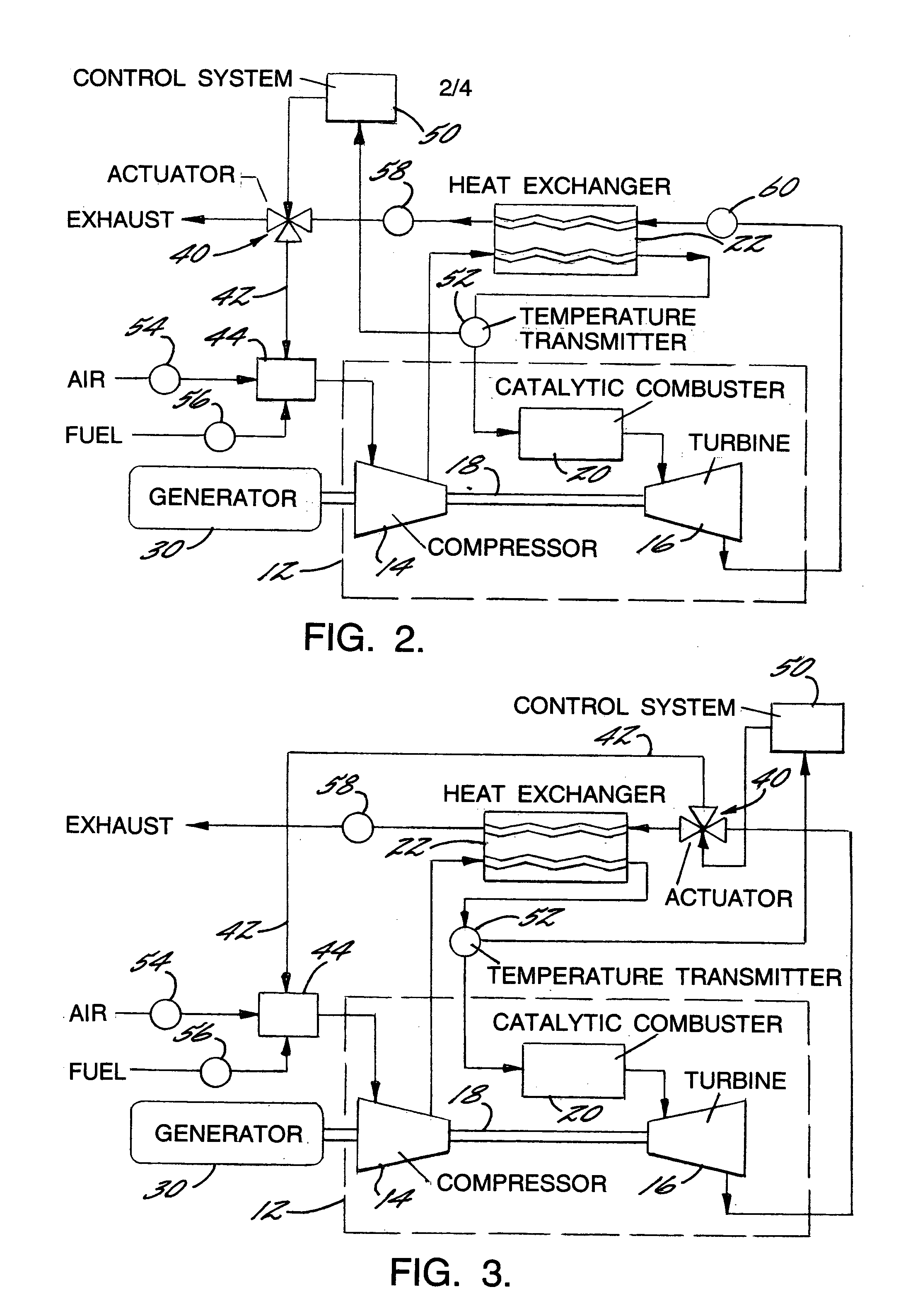
[0028]The present invention provides a gas turbine engine system and method that overcome this problem. FIG. 2 shows an electrical generator system driven by a turbine engine system in accordance with the invention. A generator 30 is driven by a turbine engine 12 having a compressor 14, turbine 16, shaft 18, and catalytic combustor 20 as previously described. A recuperator 22 is employed for pre-heating the air-fuel mixture before its introduction into the combustor, as previously described.

[0029]However, the combustor inlet temperature is regulated by the introduction of a portion of the turbine exhaust gas into the compressor. The exhaust gas has a substantially higher temperature than the ambient air entering the compressor, and therefore serves to boost the temperature of the fluid passing through the compressor, which in turn boosts the combustor inlet temperature.

[0030]Thus, the system includes an actuatable valve 40 disposed downstream of the recuperator 22 for diverting a po...

second embodiment

[0034]FIG. 3 shows the invention, generally similar to that of FIG. 2, except the valve 40 is located upstream of the recuperator 22 instead of downstream. The line 42 thus bypasses the recuperator, so the exhaust gas is not cooled in the recuperator before being recirculated. Because the temperature of the recirculated exhaust gas is higher, the relative proportion of exhaust gas that must be recirculated is lower than for the embodiment of FIG. 2, all other factors being equal. In other respects, the operation of this system is the same as that of FIG. 2.

[0035]The manner in which the exhaust gas is recirculated and mixed with the air and fuel can be varied in the practice of the invention. FIGS. 5A–C show several possibilities, although they are not exhaustive, and other variations can be used. All of these examples are based on the valve 40 being downstream of the recuperator 22, but they apply equally to systems in which the valve is upstream of the recuperator. In the embodimen...


PUM


Abstract

A recuperated gas turbine engine system and associated method employing catalytic combustion, wherein the combustor inlet temperature can be controlled to remain above the minimum required catalyst operating temperature at a wide range of operating conditions from full-load to part-load and from hot-day to cold-day conditions. The fuel is passed through the compressor along with the air and a portion of the exhaust gases from the turbine. The recirculated exhaust gas flow rate is controlled to control combustor inlet temperature.

Description

FIELD OF THE INVENTION[0001]The invention relates to recuperated gas turbine engine systems in which catalytic combustion is employed.BACKGROUND OF THE INVENTION[0002]The use of catalytic processes for combustion or oxidation is a well-known method for potentially reducing levels of nitrogen oxides (NOx) emissions from gas turbine engine systems. There are various processes for converting the chemical energy in a fuel to heat energy in the products of the conversion. The primary processes are: 1) gas phase combustion, 2) catalytic combustion, and 3) catalytic oxidation. There are also combinations of these processes, such as processes having a first stage of catalytic oxidation followed by a gas phase combustion process (often referred to as cata-thermal). In catalytic oxidation, an air-fuel mixture is oxidized in the presence of a catalyst. In all catalytic processes the catalyst allows the temperature at which oxidation takes place to be reduced relative to non-catalytic combustio...

Claims


Application Information

Patent Timeline
Patent Type & Authority Patents(United States)
IPC IPC(8): F23R3/34F23R3/40F23C9/00
CPCF23C9/00F23R3/40F23C2202/10F23N2041/20F23N2037/12F23N2237/12F23N2241/20F23N5/00F23N5/18
Inventor BELOKON, ALEXANDER A.TOUCHTON, GEORGE L.
Owner MES INT INC
Why Eureka
Try Eureka