Frequency Identification for Microwave Ablation Probes

a technology of frequency identification and ablation probes, which is applied in the field of microwave antennas, can solve the problems of inefficient application of microwave energy, achieve the effects of reducing ablation time, improving ablation size, and maximizing the efficiency of the antenna assembly

Active Publication Date: 2010-10-14
TYCO HEALTHCARE GRP LP
View PDF3 Cites 214 Cited by
  • Summary
  • Abstract
  • Description
  • Claims
  • Application Information

AI Technical Summary

Benefits of technology

[0007]The present disclosure provides for a system and method that allow for identification of specific operational frequency of each microwave antenna assembly. The operational frequency may be encoded as a resistance value or in memory available for measurement or reading by a microwave ablation generator. The generator may then be configured to substantially match the operational frequency to the optimal frequency of each antenna assembly. Matching the output frequency to optimal frequency maximizes antenna assembly's efficiency and energy delivery to the target tissue, thereby improving ablation size and reducing the ablation time. Utilizing optimal frequency for each antenna assembly also reduces reflected energy from the assembly back to the generator, which in turn, reduces heating of the entire system. Further, the system and method of the present disclosure provide for an additional quality check of the antenna assembly during the manufacturing process, allowing for discarding of any antenna assemblies whose optimal frequency falls outside an expected deviation from a desired operational range. In addition, the system and method according to the present disclosure allow for use of antenna assemblies with a wider range of manufacturing tolerances, since the operational frequency may be used to tune the generator to a desired frequency that best matches the determined frequency of the antenna assembly. Without this tuning capability and using a fixed frequency generator, the optimal operating frequency for a given antenna might be outside the usable frequency range of the generator, which results in inefficient application of microwave energy.

Problems solved by technology

Without this tuning capability and using a fixed frequency generator, the optimal operating frequency for a given antenna might be outside the usable frequency range of the generator, which results in inefficient application of microwave energy.

Method used


Image

  • Frequency Identification for Microwave Ablation Probes
  • Frequency Identification for Microwave Ablation Probes
  • Frequency Identification for Microwave Ablation Probes

Examples


Embodiment Construction

[0016]Particular embodiments of the present disclosure will be described herein below with reference to the accompanying drawings. In the following description, well-known functions or constructions are not described in detail to avoid obscuring the present disclosure in unnecessary detail.

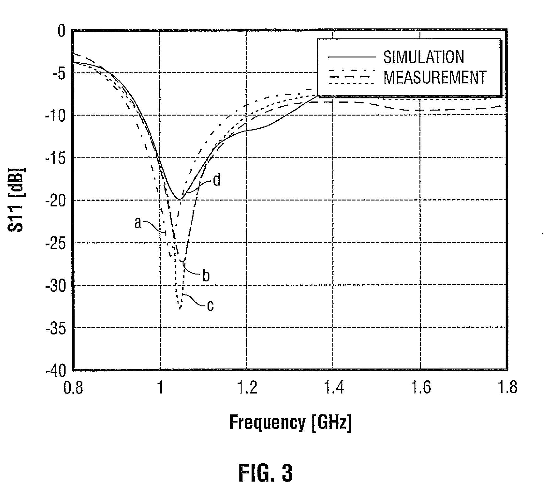
[0017]Microwave antenna assemblies are typically resonant structures, which operate most efficiently at a particular frequency. In other words, due to manufacturing tolerance limitations, each microwave antenna assembly has a unique optimal operational frequency. The present disclosure provides for a system and method for determining the operational frequency of the microwave antenna assembly and providing the optimal frequency to a microwave generator, which then adjusts output of the microwave energy accordingly to substantially match the optimal frequency.

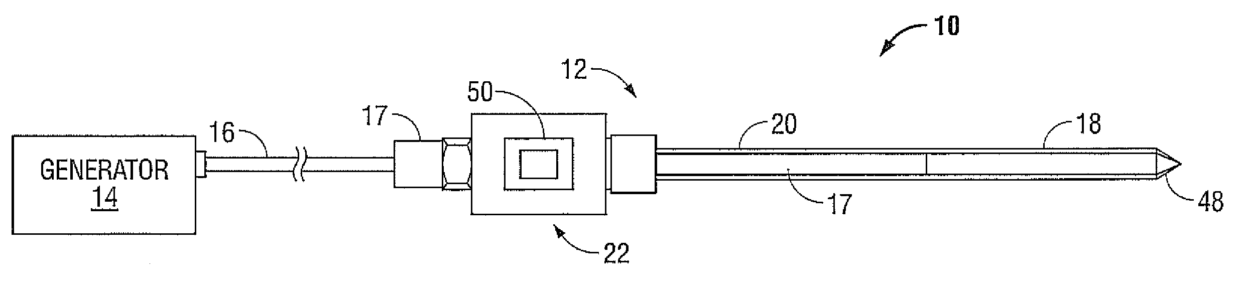
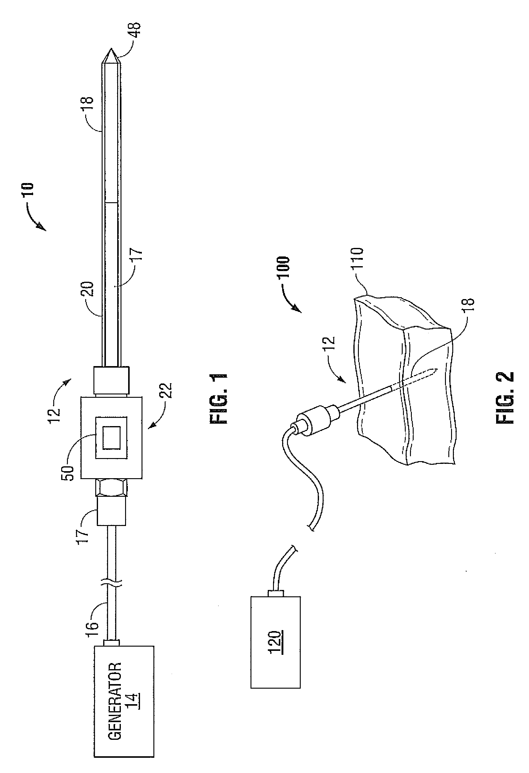
[0018]FIG. 1 shows a microwave ablation system 10 that includes a microwave antenna assembly 12 coupled to a microwave generator 14 via a fle...


PUM


Abstract

A microwave ablation system is disclosed. The system includes a microwave antenna assembly that includes an identification device configured to store an optimal frequency of the microwave antenna assembly. The system also includes a generator configured to couple to the microwave antenna assembly and to output microwave energy at an operational frequency. The generator is further configured to read the optimal frequency from the identification device and to configure the operational frequency to substantially match the optimal frequency.

Description

BACKGROUND[0001]1. Technical Field[0002]The present disclosure relates generally to microwave antennas used in tissue ablation procedures. More particularly, the present disclosure is directed to optimal frequency identification for microwave ablation antennas.[0003]2. Background of Related Art[0004]Treatment of certain diseases requires destruction of malignant tissue growths (e.g., tumors). It is known that tumor cells denature at elevated temperatures that are slightly lower than temperatures injurious to surrounding healthy cells. Therefore, known treatment methods, such as hyperthermia therapy, heat tumor cells to temperatures above 41° C., while maintaining adjacent healthy cells at lower temperatures to avoid irreversible cell damage. Such methods involve applying electromagnetic radiation to heat tissue and include ablation and coagulation of tissue. In particular, microwave energy is used to coagulate and / or ablate tissue to denature or kill the cancerous cells.[0005]Microw...

Claims


Application Information

Patent Timeline
Patent Type & Authority Applications(United States)
IPC IPC(8): A61B18/18
CPCA61B18/18A61B18/1815A61B2019/448A61B2018/00988A61B2018/1869A61B2018/00196A61B90/98
Inventor JENSEN, JEFFREY L.BRANNAN, JOSEPH D.
Owner TYCO HEALTHCARE GRP LP
Why Eureka
Try Eureka