Power supply system and method of controlling power supply system

a power supply system and power supply technology, applied in the field of power supply systems, can solve problems such as possible decreases in charging efficiency, and achieve the effect of maintaining or improving power supply efficiency and maximizing power supply efficiency

Active Publication Date: 2010-05-20
TOYOTA JIDOSHA KK
View PDF99 Cites 232 Cited by
  • Summary
  • Abstract
  • Description
  • Claims
  • Application Information

AI Technical Summary

Benefits of technology

[0016]A fourth aspect of the invention relates to a method of controlling a power supply system that includes a power supply coil and a power supply-side resonance coil that are provided at a facility; and a power receiving coil and a power receiving-side resonance coil that are provided for a mobile unit. The method includes: detecting a power supply efficiency that indicates a transmission efficiency of electric power; and, after the mobile unit stops around the facility, adjusting a relative position between the power supply coil and

Problems solved by technology

In addition, when a battery mounted on a mobile unit such as a veh

Method used


Image

  • Power supply system and method of controlling power supply system
  • Power supply system and method of controlling power supply system
  • Power supply system and method of controlling power supply system

Examples


Embodiment Construction

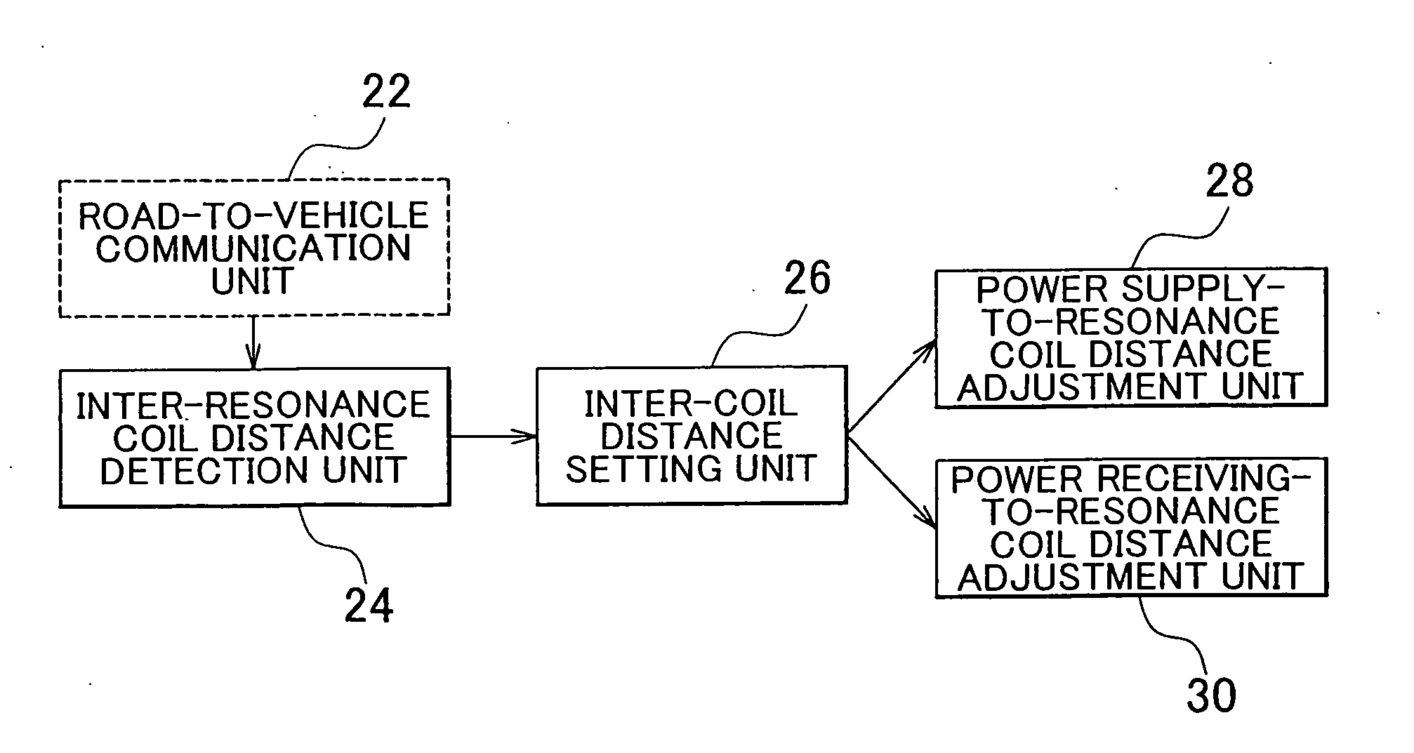
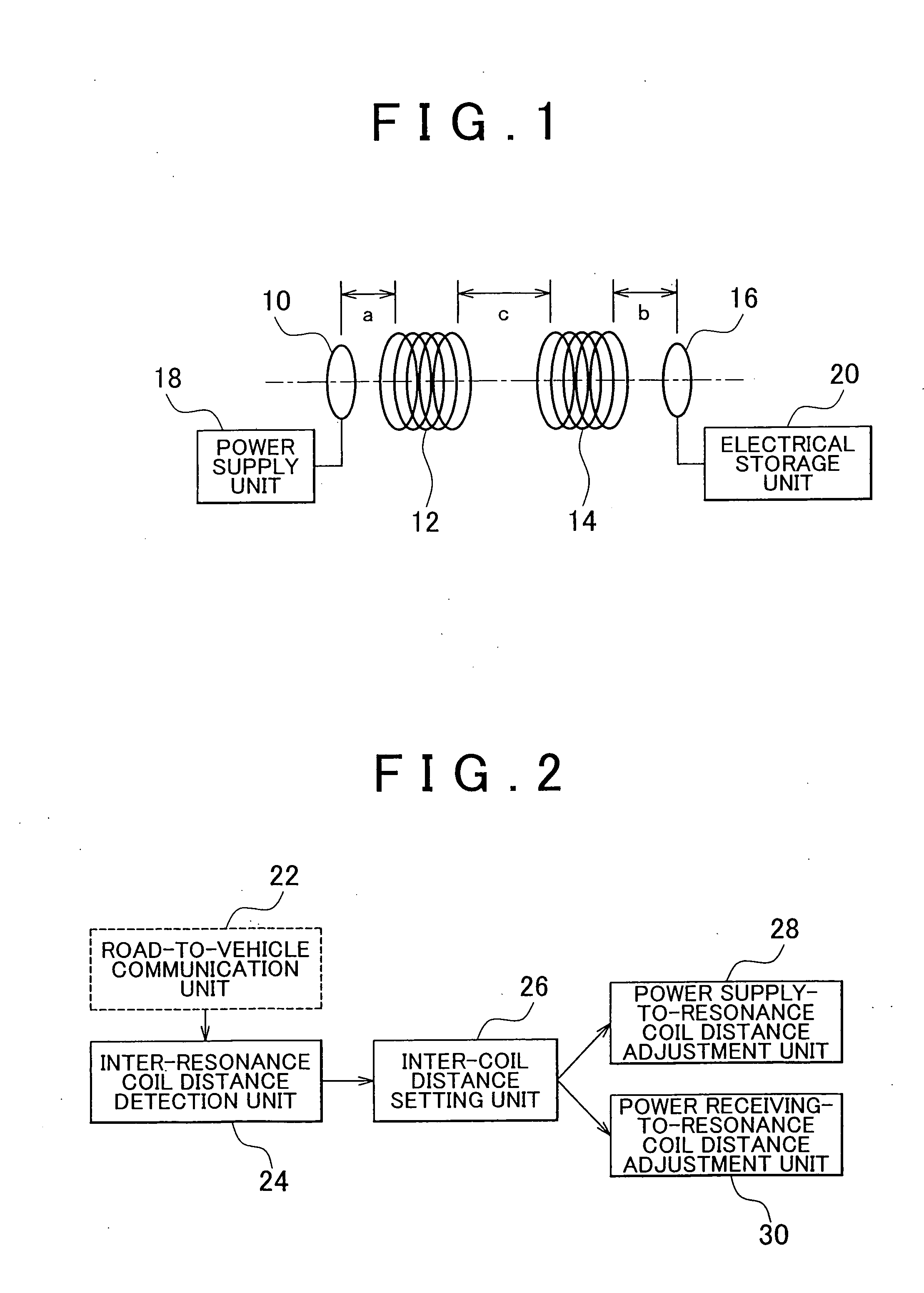
[0032]FIG. 1 shows a configuration block diagram of a power supply system according to an embodiment of the invention. The power supply system includes a power supply coil 10, a power supply-side resonance coil 12, a power receiving-side resonance coil 14 and a power receiving coil 16. The power supply coil 10 and the power supply-side resonance coil 12 serve as a primary-side coil and are provided at a facility, such as a power supply station. The power receiving-side resonance coil 14 and the power receiving coil 16 serve as a secondary-side coil and are provided for a mobile unit, such as a vehicle. The power supply coil 10 is supplied with electric power from a power supply unit 18. Then, the supplied electric power is supplied from the power supply coil 10 to the power supply-side resonance coil 12, from the power supply-side resonance coil 12 to the power receiving-side resonance coil 14 and further from the power receiving-side resonance coil 14 to the power receiving coil 16...


PUM


Abstract

A power supply system that includes: a power supply coil and a power supply-side resonance coil that are provided at a facility; a power receiving coil and a power receiving-side resonance coil that are provided for a mobile unit; a power supply-side detection unit that detects a position of the power supply-side resonance coil; a power receiving-side detection unit that detects a position of the power receiving-side resonance coil; and an adjustment unit that adjusts a relative position of the power supply coil with respect to the power supply-side resonance coil and a relative position of the power receiving coil with respect to the power receiving-side resonance coil on the basis of the position of the power supply-side resonance coil and the position of the power receiving-side resonance coil.

Description

INCORPORATION BY REFERENCE[0001]The disclosure of Japanese Patent Application No. 2008-293005 filed on Nov. 17, 2008, including the specification, drawings and abstract is incorporated herein by reference in its entirety.BACKGROUND OF THE INVENTION[0002]1. Field of the Invention[0003]The invention relates to a power supply system and, more particularly, to a system that supplies electric power from a power supply coil, provided at a facility, to a power receiving coil, provided for a mobile unit such as a vehicle, in a non-contact manner and a method of controlling the system.[0004]2. Description of the Related Art[0005]There is known a non-contact power supply system that uses electromagnetic induction. For example, Japanese Patent Application Publication No. 2006-345588 (JP-A-2006-345588) describes a non-contact power supply device and a power supply system for an autonomous mobile unit. The non-contact power supply device described in JP-A-2006-345588 includes a primary coil that...

Claims


Application Information

Patent Timeline
IPC IPC(8): H01F29/12B60L5/00
CPCB60L11/182B60L11/1829H01F38/14H02J5/005Y02T90/121Y02T90/12Y02T90/122Y02T90/125Y02T90/14Y02T10/7005Y02T10/7072B60L53/38H02J7/00712B60L53/126Y02T10/70H02J50/80H02J50/90H02J50/12H02J7/0049
Inventor AMANO, YASUSHIICHIKAWA, SHINJI
Owner TOYOTA JIDOSHA KK
Why Eureka
Try Eureka