Organic Rankine Cycle Mechanically and Thermally Coupled to an Engine Driving a Common Load

a rankine cycle and engine technology, applied in mechanical equipment, machines/engines, steam engine plants, etc., can solve the problems of inability to achieve maximum efficiency with such a system, inability to achieve power combining circuitry, and inability to meet the requirements of the system

Inactive Publication Date: 2009-08-27
UNITED TECH CORP
View PDF17 Cites 239 Cited by
  • Summary
  • Abstract
  • Description
  • Claims
  • Application Information

AI Technical Summary

Benefits of technology

[0009]Aspects of the invention include: utilizing substantially all the heat that must be eliminated from an engine driving a load in an associated ORC system which is thermally and mechanically coupled with the engine; utilizing an ORC system to eliminate substantially all of the heat which must be extracted from an engine driving a load; operating a single mechanical load directly with mechanical power provided by an engine and an ORC system which is mechanically and thermally coupled thereto; providing an engine sharing a mechanical load with an ORC system, without the need for redundant replicated equipment; driving a single generator with an engine and ORC system mechanically coupled thereto without the need for complicated load. sharing, power combining apparatus.
[0010]In accordance with the invention, the shaft of an engine is mechanically coupled with a shaft of a turbine of an organic Rankine cycle system, substantially all of engine waste heat being utilized to evaporate the organic Rankine cycle fluid, thereby maximizing the efficiency of the combined system. In further accord with the invention, condensed organic Rankine cycle fluid flows through various engine-related coolers, including one or more of: intake air (charge air) cooler; engine coolant; engine oil cooler; EGR cooler; as well as using engine exhaust in the evaporator.
[0012]The utilization of the liquid-to-liquid heat exchangers 46-48 replaces large liquid-to-air heat exchangers and their associated fans, with considerable reduction in cost, and / or an in-coolant engine oil cooler.

Problems solved by technology

However, atmospheric emissions such as nitrogen oxides, (NOx), carbon monoxide (CO) and particulates have always been an issue with these engines.
This approach requires separate, redundant generators, control equipment and power conversion components; the power combining circuitry is an additional burden to such a system.
Therefore, maximal efficiency cannot even be approached with such a system.

Method used


Image

  • Organic Rankine Cycle Mechanically and Thermally Coupled to an Engine Driving a Common Load
  • Organic Rankine Cycle Mechanically and Thermally Coupled to an Engine Driving a Common Load
  • Organic Rankine Cycle Mechanically and Thermally Coupled to an Engine Driving a Common Load

Examples


Embodiment Construction

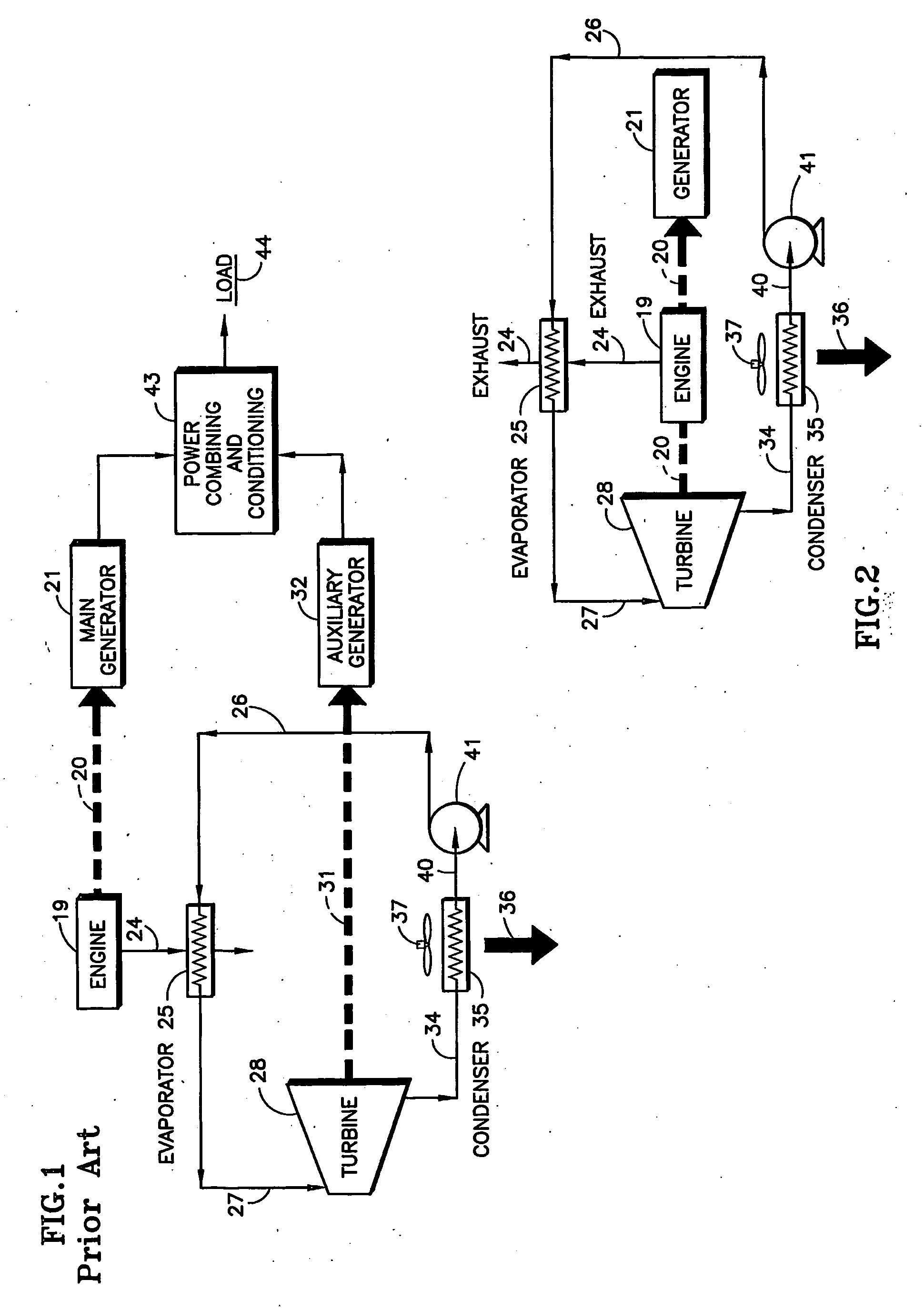
[0031]The simplest embodiment of the present invention, illustrated in FIG. 2, eliminates the need for an auxiliary generator 32 (FIG. 1) and the power combining processing associated therewith. This is achieved by causing the turbine (28) to be journaled on the same shaft 20 along with the engine 19 and a single generator 21. With the turbine rotor directly coupled to the engine shaft, the engine is started first, and actually drives the turbine as a load until the generated heat in the engine becomes sufficient to cause the ORC turbine 28 to contribute torque to the shaft 20.

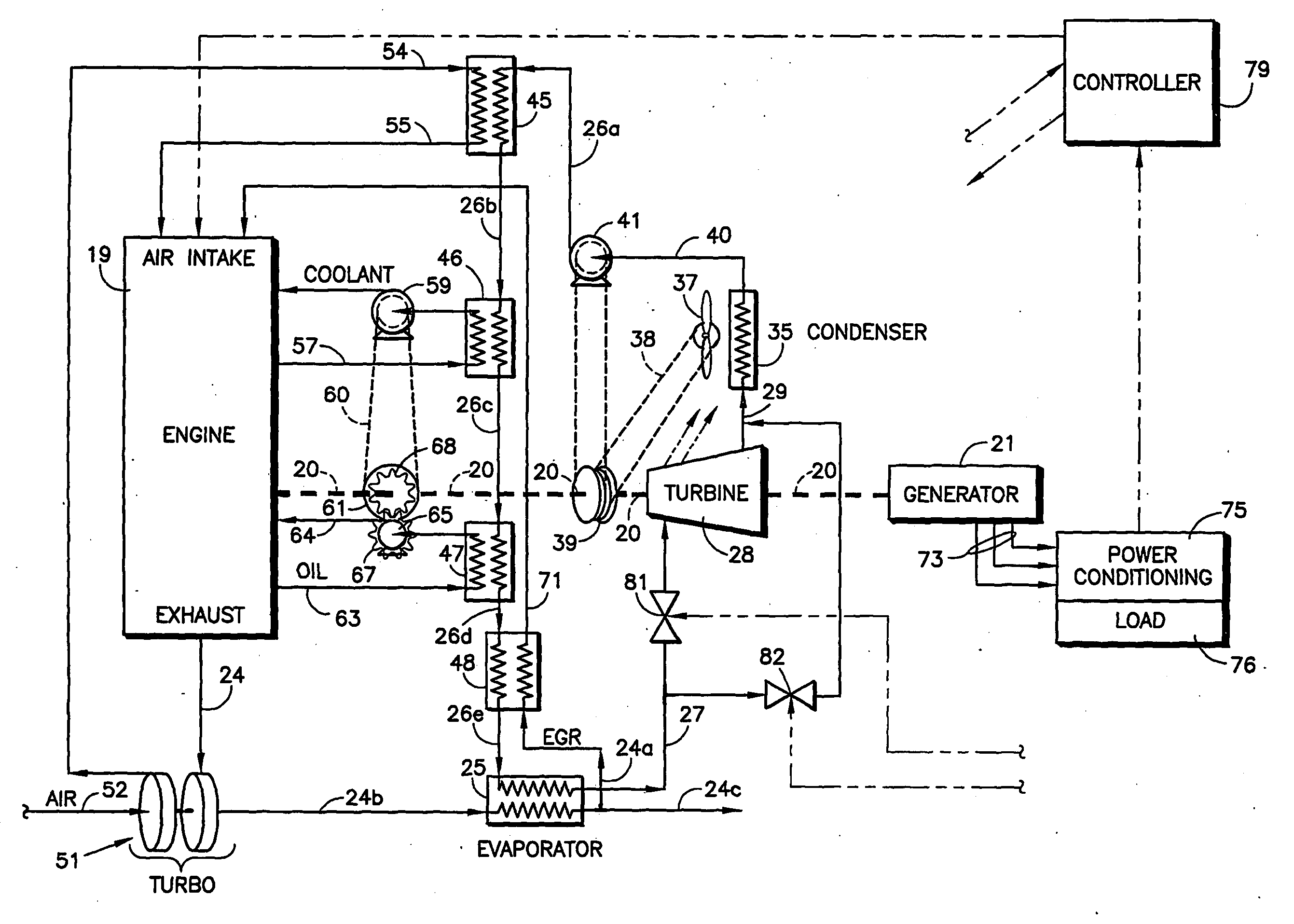
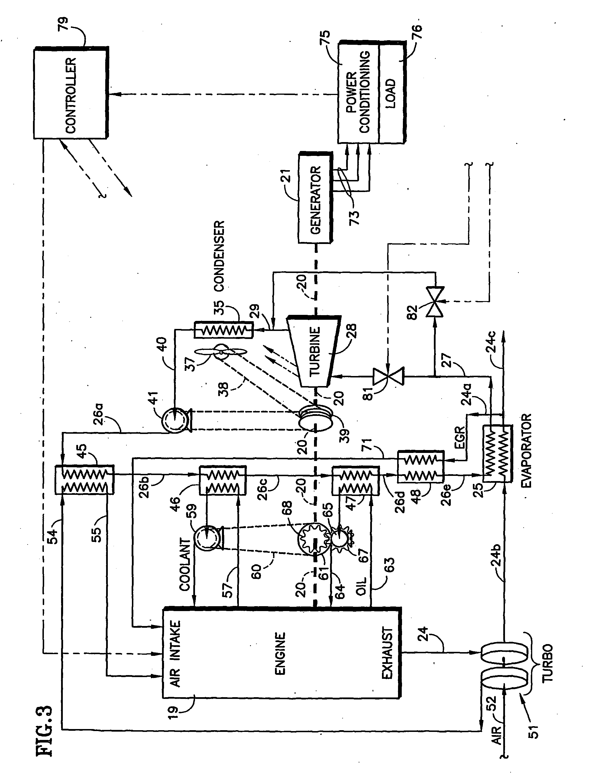
[0032]A simplified illustrative representation of a reciprocating engine with an organic Rankine cycle subsystem utilizing substantially all of the waste engine heat is shown in FIG. 3. Therein, instead of utilizing only exhaust heat in an evaporator, there are a plurality of preheaters 45-48, each consisting of a heat exchanger with the ORC fluid being warmed to increasing temperatures by engine waste heat.

[0...


PUM


Abstract

The shaft (20) of an engine (19) is coupled to a turbine (28) of an organic Rankine cycle subsystem which extracts heat (45-48, 25) from engine intake air, coolant, oil, EGR and exhaust. Bypass valves (92,94, 96, 99) control engine temperatures. Turbine pressure drop is controlled via a bypass valve (82) or a mass flow control valve (113). A refrigeration subsystem having a compressor (107) coupled to the engine shaft uses its evaporator (45a) to cool engine intake air. The ORC evaporator (25a) may comprise a muffler including pressure pulse reducing fins (121, 122), some of which have NOx and / or particulate reducing catalysts thereon.

Description

[0001]The benefit of U.S. provisional application No. 60 / 691,067 filed Jun. 16, 2005 is claimed.TECHNICAL FIELD[0002]This invention relates to an organic Rankine cycle (ORC) system in which the turbine mechanical output is coupled to a common load with an engine mechanical energy output, the ORC utilizing the engine's waste thermal energy to evaporate the ORC fluid as it cools the engine. An electric generator or other load may be driven by the combined engine / ORC system of the invention.BACKGROUND ART[0003]Efficient power generation systems that provide low-cost energy with minimum environmental impact, and that can be readily and rapidly sited as stand-alone units for integration into the existing power grid, are appropriate for solving critical power needs in many areas. Reciprocating engines are the most common and most technically mature of these distributed energy resources, but turbines may also be used. These engines can generate electricity with efficiencies of 25% to 40% u...

Claims


Application Information

Patent Timeline
Patent Type & Authority Applications(United States)
IPC IPC(8): F01K23/06F02G5/04
CPCF01K23/065F01K23/06F02G5/04F01K25/00F01K7/00
Inventor RADCLIFF, THOMAS D.BIEDERMAN, BRUCE P.MCCORD, KENT R.ZHANG, LILI
Owner UNITED TECH CORP
Why Eureka
Try Eureka