Hover Installed Renewable Energy Tower

a renewable energy and tower technology, applied in the field of towers, can solve the problems of requiring additional cost and expertise related to raising a large platform, requiring skill, and requiring access to heavier equipment,

Inactive Publication Date: 2007-04-26
MARTELON DAVID R
View PDF13 Cites 52 Cited by
  • Summary
  • Abstract
  • Description
  • Claims
  • Application Information

AI Technical Summary

Benefits of technology

[0008] The adaptability of the towers of the present invention comes into play in regional, or other markets where there is obvious weighted consideration to one or the other technologies of solar or wind. For example, in the sunbelt states it may be advantageous to adapt the tower to augment it with additional photovoltaic panels instead of installing the wind turbine. Conversely, where sunlight is not as prevalent it is possible to install one or more wind turbines and avoid the cost of solar panel installations.
[0009] Additionally, tinker-toy construction of the towers allows for enhancement or upgrade of individual pieces without a complete replacement. For example, as photovoltaic and / or turbine technologies improve, it is possible to exchange these individual components with product upgrades to gain an increase in output efficiency without reconstructing the entire renewable energy tower. Another way that output can be maximized is by easily adapting the product to the various tracker technologies that exist in the market, allowing for a number of freestanding solar panels that can track the path of the sun, enhancing the solar input and resultant output.
[0011] The hybrid nature of the renewable energy towers of the present invention provides a complementarity in that each of the individual component types work together to compensate one for the other. Typically, when the sun is not shining, the wind is operating at or near maximum capacity. This trend is most evident from season to season, which allows for a consistent expectation of year round renewable energy production.
[0012] The invention also provides a fundamental improvement in how wind turbines and photovoltaic arrays are raised. The towers of the present invention provide a hover-up installation improvement. This levitation technique allows all component integration to occur at ground level alleviating the installer of difficult elevated integrations or manipulations. Together, these installation improvements significantly reduce the risk, cost and technical knowledge necessary with traditional installations of elevated components. This hover-up installation technique also enables the easy installation of towers with increased height.
[0014] By simply reversing the installation process it is easy to upgrade and maintain the components on the tower, which is a common need in the case of micro or small turbines.
[0015] Prior art devices are typically limited in height to roughly forty feet by the structural aspects of the inner support beam. But because wind applications increase on a better than linear curve with an increase in height, elevation above forty feet is beneficial for the use of wind turbines. In order to allow for an increase in height while remaining freestanding or non-guyed, a further installation enhancement is provided in this disclosure. With the amendment of an external hover track to the existing inner support beam, it is possible to use a first, manually-installed inner support beam to install a replicated version of that beam as an adjoining outer shell. In this way, it is possible to continue to add additional layers of inner support, thus allowing for an increase in height of the tower as a whole.

Problems solved by technology

Many residences lack the potential for employing solar energy in this traditional form because they lack an adequate sun-exposure facing roof surface or natural landscape elements that prevent adequate sun exposure.
Top-of-pole mounted arrays often suffer space and aesthetic challenges as they are composed of a very large solar platform, thereby requiring additional cost and expertise related to raising a large platform.
Both of these methods require a high cost, skill and necessitate access to heavier equipment.
These requirements lead to market limitations, add significantly to project risk and the need for very specific installation expertise.

Method used


Image

  • Hover Installed Renewable Energy Tower
  • Hover Installed Renewable Energy Tower
  • Hover Installed Renewable Energy Tower

Examples


Embodiment Construction

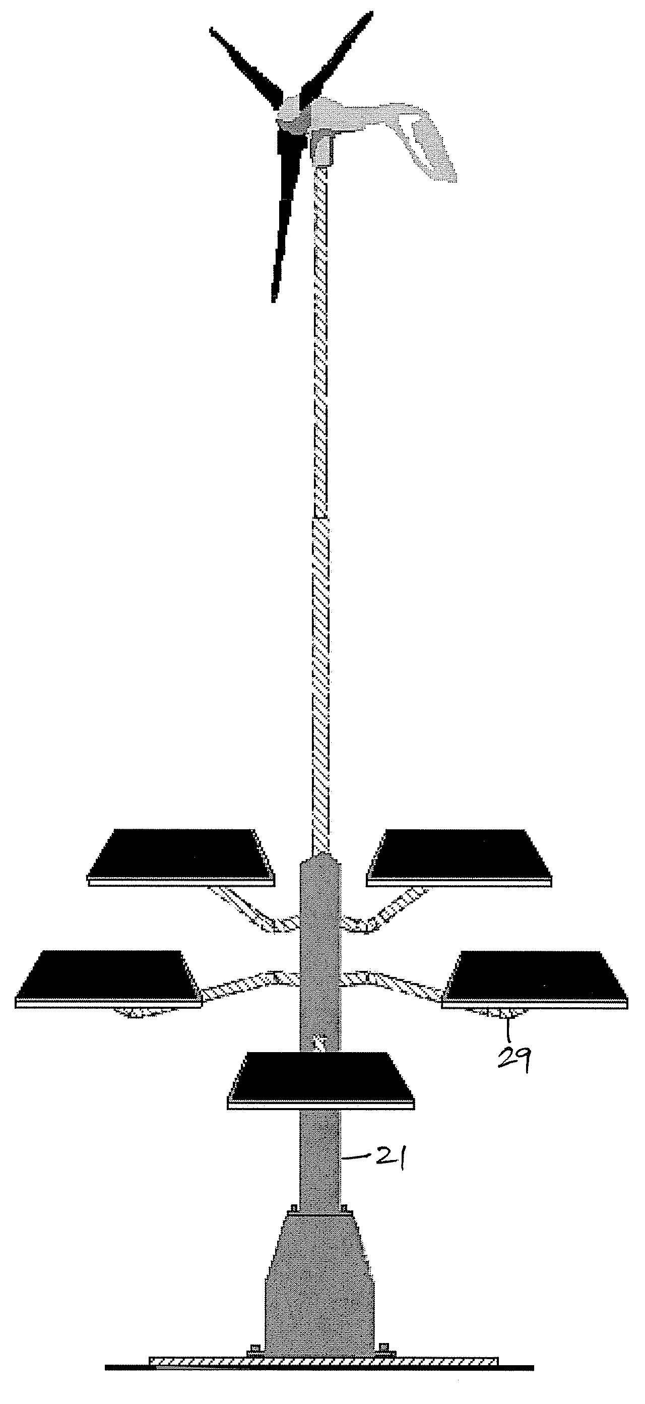
[0040] The present invention is drawn to a renewable energy tower that is adapted to support and positioning of renewable energy components. The towers of the present invention are adaptable to many configurations and components, easy substitution and maintenance of these components, stand-alone operation, hybrid operation of multiple components, simplified and inexpensive installation and, optionally, increased height over the related prior art technologies.

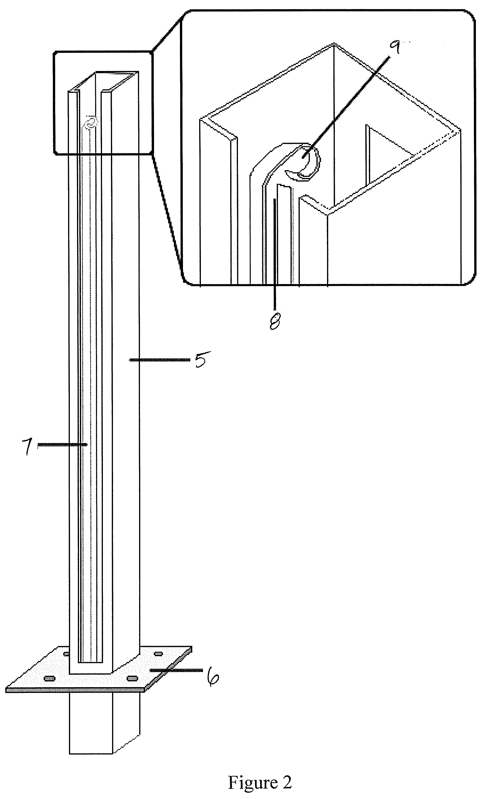
[0041] The figures that form part of this disclosure are referred to in the following description. The figures show several specific embodiments of the inventive tower technology with integrated renewable energy components. The figures also demonstrate the assembly process, providing a detailed understanding of the components at each layer.

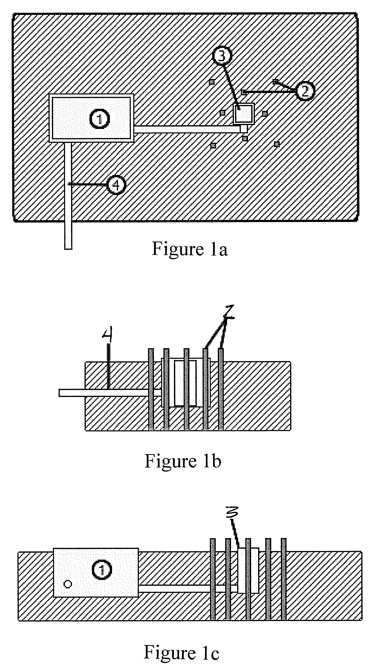
[0042]FIG. 1a shows a cement foundation for a renewable energy tower of the present invention from a top viewpoint. The primary function of the foundation pad is structural support and ease ...


PUM


Abstract

The invention provides a scaleable tower that adapts to the technologies of photovoltaic panels and micro to small turbine(s), in multiple configurations, raised in a hover-up manner.

Description

CROSS REFERENCE TO RELATED APPLICATION [0001] This application claims the benefit of priority under 35 U.S.C. § 119(e) to U.S. Provisional Patent Application Ser. No. 60 / 723,816 filed Oct. 4, 2005, which is incorporated herein by reference.FIELD OF THE INVENTION [0002] The invention relates to a tower that supports multiple configurations of renewable energy components and an improved system of installation. The tower and the configurations supported are particularly suited to systems for the residential consumer market. BACKGROUND OF THE INVENTION [0003] The individual technologies of photovoltaic and micro to small turbines have been steadily improving over the course of the last twenty years. The improvements in output and efficiency of these technologies, combined with an increase in manufacturer competition and a decrease in the cost of production due to process improvements, has yielded a much lower consumer cost. This, when coupled with the crossing trends of an increase in u...

Claims


Application Information

Patent Timeline
Patent Type & Authority Applications(United States)
IPC IPC(8): F03D9/00
CPCF03D9/007F05B2230/60F05B2240/40F05B2240/912F05B2240/916Y02E10/728Y02E10/50Y02P70/50Y02E10/72F03D13/20H02S10/12
Inventor MARTELON, DAVID R.
Owner MARTELON DAVID R
Why Eureka
Try Eureka