Microstructure with enlarged mass and electrode area for kinetic to electrical energy conversion

a microstructure and electrode area technology, applied in the field of microstructures, can solve the problems of large mass, and achieve the effects of maximizing energy output per cycle, reducing energy consumption, and increasing electrode area

Inactive Publication Date: 2011-02-01
STICHTING IMEC NEDERLAND
View PDF4 Cites 49 Cited by
  • Summary
  • Abstract
  • Description
  • Claims
  • Application Information

AI Technical Summary

Benefits of technology

[0013]At least some of the embodiments of the present disclosure to provide a compact micromachined device for electrostatic conversion of kinetic energy into electrical energy, such as e.g. a micromachined electrostatic scavenger, wherein the energy output per cycle may be maximized with less need for making a trade-off between the size of the seismic mass and the size of the electrodes. The present application provides a microstructure as set out in the claims. Some embodiments involve providing a microstructure for kinetic to electrical energy conversion wherein a seismic mass and comb electrodes are vertically integrated. The fingers of the movable electrode are vertically connected to the seismic mass such that the seismic mass is located out of the plane of the electrodes. Because of the vertical integration, the whole die area can be used for forming the electrodes. For a given die size this leads to a bigger electrode area as compared to prior art solutions, and thus to a higher power output. In addition the seismic mass may occupy the whole die area, thus leading to a bigger mass than in prior art solutions or leading to a more compact device than in prior art solutions. With a bigger mass, higher conversion efficiencies may be obtained and lower operating frequencies are enabled, e.g. operating frequencies corresponding to typical ambient vibrations (e.g. frequencies in the range between 50 Hz and 350 Hz).

Problems solved by technology

In addition the seismic mass may occupy the whole die area, thus leading to a bigger mass than in prior art solutions or leading to a more compact device than in prior art solutions.

Method used


Image

  • Microstructure with enlarged mass and electrode area for kinetic to electrical energy conversion
  • Microstructure with enlarged mass and electrode area for kinetic to electrical energy conversion
  • Microstructure with enlarged mass and electrode area for kinetic to electrical energy conversion

Examples


Embodiment Construction

[0042]A number of the disclosed embodiments involve a design and / or a manufacturing method for a compact microstructure that is suitable for electrostatic conversion of kinetic energy into electrical energy. Such a microstructure may be used in devices wherein electrostatic conversion between kinetic energy and electrical energy occurs, such as for example in micromachined electrostatic energy scavengers or accelerometers. Some embodiments further involve a method for tuning a resonance frequency of such a microstructure. In this description, the design and the manufacturing methods of the microstructure are described for a gap-closing electrostatic energy scavenger configuration. However, the microstructure may be used in other energy converting devices.

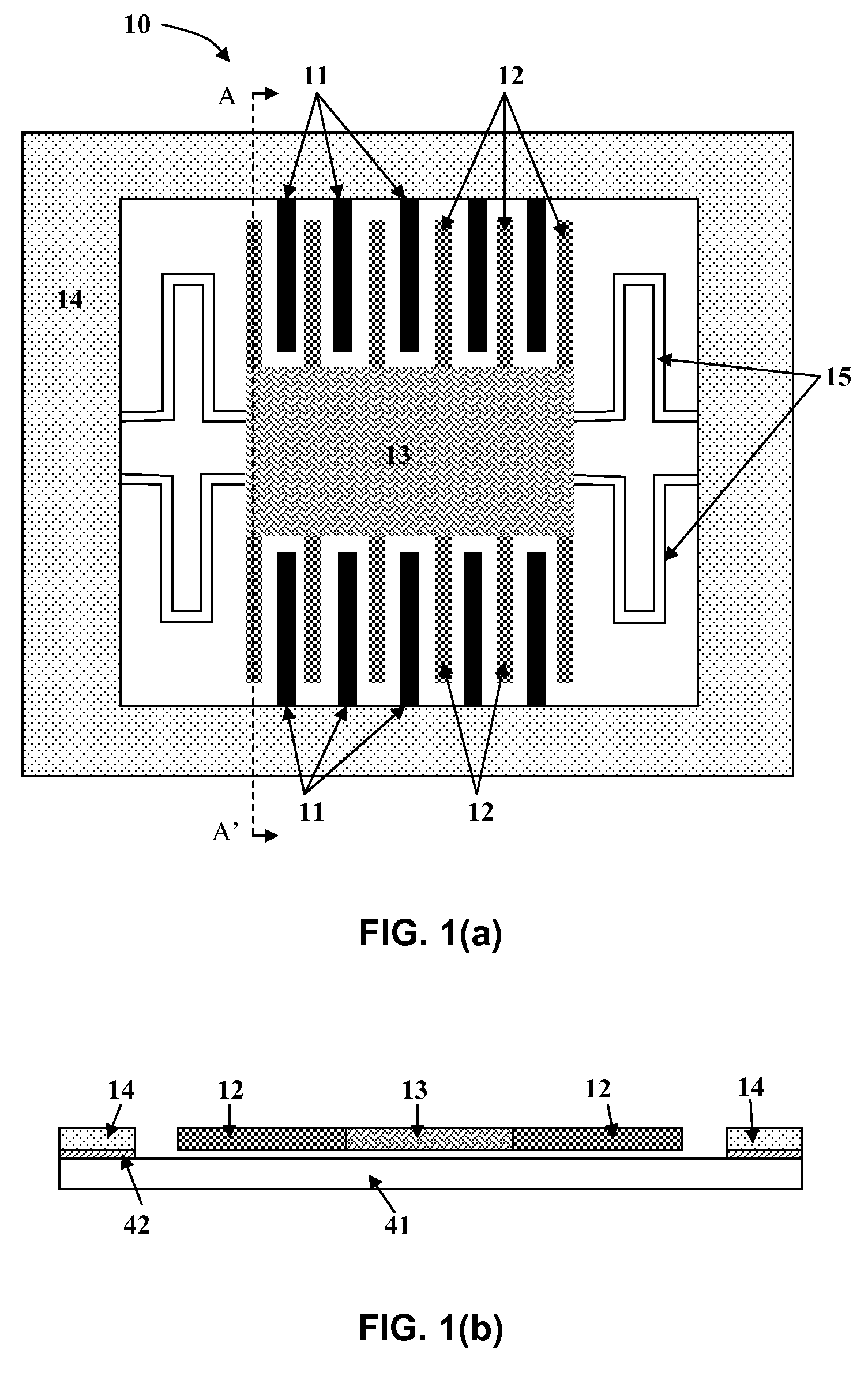
[0043]FIG. 1(a) schematically shows a prior art gap-closing electrostatic scavenger 10. The energy scavenging principle of such a gap-closing electrostatic scavenger 10 is based on using vibrational energy to charge a storage capaci...


PUM


Abstract

A microstructure has a substrate, a fixed electrode having a plurality of fixed fingers fixed to the substrate, a movable electrode having a body (28) and a plurality of fingers (22) extending from the body, the movable electrode being movable relative to the fixed fingers to vary a capacitance of the electrodes. The fixed fingers (21) extend in a first plane parallel to a main surface of the substrate, wherein the body of the movable electrode extends in a second plane adjacent to the first plane so that the body faces at least some of the plurality of fixed fingers. Such vertical integration can help enable such devices to be made more compact.

Description

CROSS-REFERENCE TO RELATED APPLICATIONS[0001]This application claims priority to U.S. Provisional Application Ser. No. 60 / 991,153 filed Nov. 29, 2007 and U.S. Provisional Application Ser. No. 61 / 097,448 filed Sep. 16, 2008, the contents of which are incorporated by reference herein in its entirety.TECHNICAL FIELD OF THE INVENTION[0002]This disclosure relates to microstructures, some used as energy converting devices, such as energy scavengers, based on the conversion of kinetic energy into electrical energy. More particularly it relates to micromachined electrostatic energy converting devices, such as electrostatic scavengers, and to methods for manufacturing such micromachined electrostatic energy converting devices.BACKGROUND OF THE INVENTION[0003]Future wireless sensor networks will comprise sensor nodes which occupy a volume of typically a few cm3. The scaling down of batteries for powering these sensor nodes faces technological restrictions as well as a loss in storage density....

Claims


Application Information

Patent Timeline
Patent Type & Authority Patents(United States)
IPC IPC(8): H01L27/14
CPCB81B3/0021H02N11/002H02N1/06H02N1/08
Inventor HOHLFELD, DENNISGOEDBLOED, MARTIJN
Owner STICHTING IMEC NEDERLAND
Why Eureka
Try Eureka