

Synchronous Machine Control Apparatus
a control apparatus and synchronous machine technology, applied in the direction of electric generator control, dynamo-electric converter control, dynamo-electric gear control, etc., can solve the problems of difficult to control the armature voltage to match a desired value, and difficult to control the motor torque with high precision by conventional control methods
- Summary
- Abstract
- Description
- Claims
- Application Information
AI Technical Summary
Benefits of technology
Problems solved by technology
Method used
Image

Examples
first embodiment
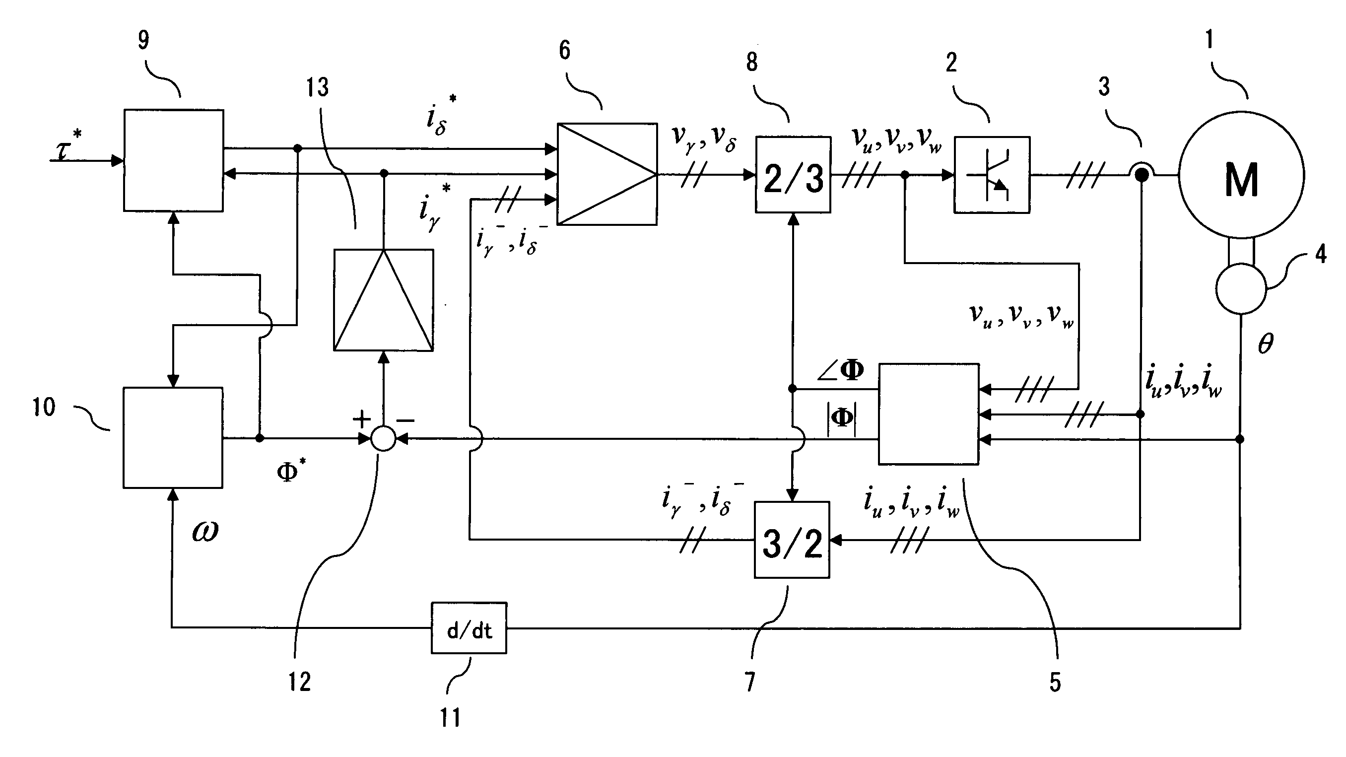
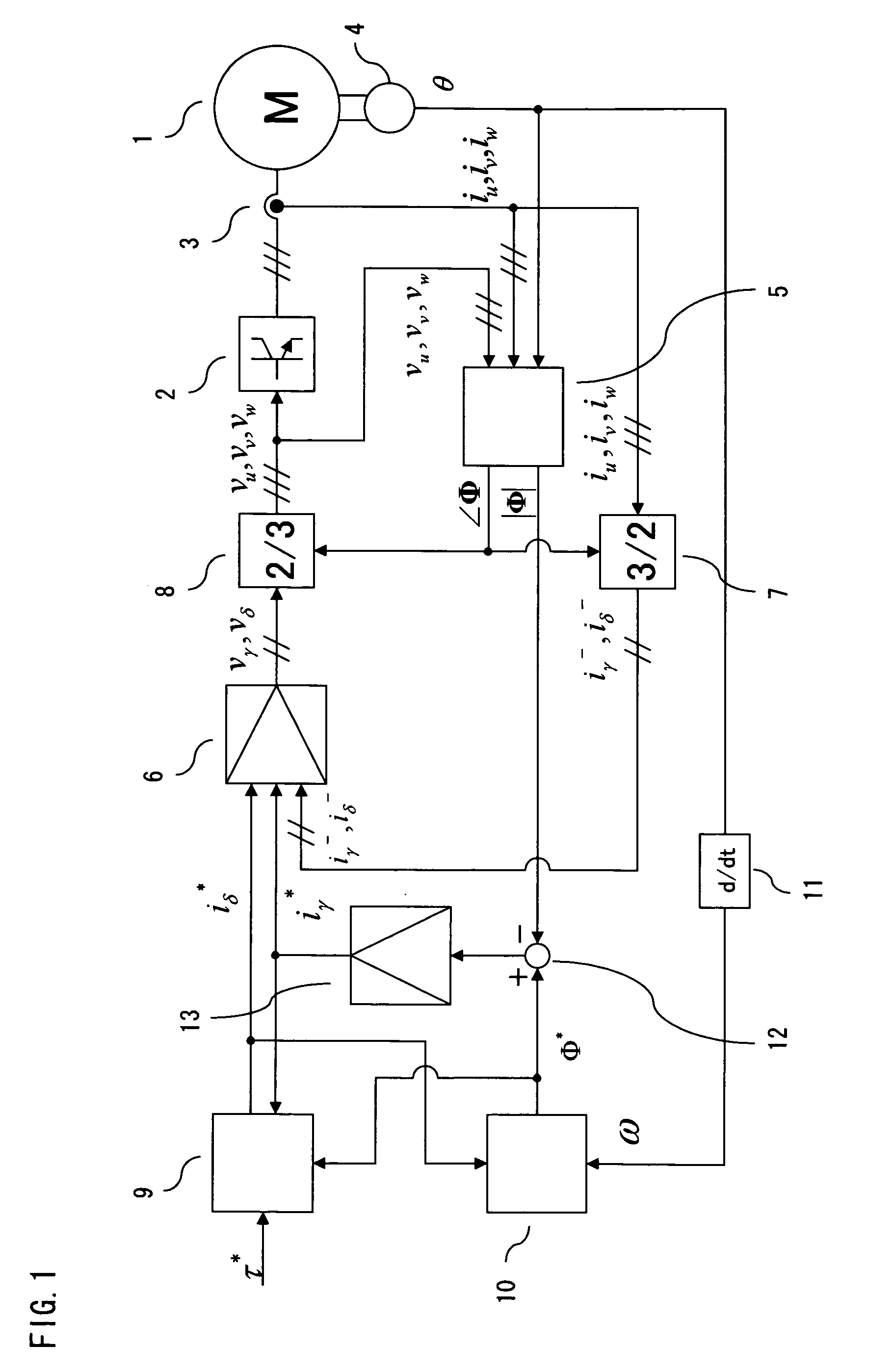
[0011]FIG. 1 is a configuration diagram showing a synchronous machine control apparatus according to a first embodiment of the present invention. A synchronous machine 1 is driven with armature windings thereof connected to a three-phase drive circuit 2 which works as a power conversion unit. A current flowing through each armature winding is detected by a current sensor 3. Also, rotor phase (electrical angle) θ of the synchronous machine 1 is detected by a rotor position sensor 4.
[0012]As will be later discussed with reference to FIGS. 6 and 7, a flux calculator 5 calculates the magnitude |Φ| and phase ∠Φ of interlinked armature flux from three-phase armature current feedback values iu, iv, iw and three-phase voltage commands vu*, vv*, vw* (which are written in simplified forms as vu, vv, vw in the Figure), for example.
[0013]Since armature currents are controlled on two axes, that is, the direction (γ-axis) of the phase ∠Φ of the interlinked armature flux and a direction (δ-axis) p...
second embodiment
[0043]FIG. 8 is a configuration diagram showing a synchronous machine control apparatus according to a second embodiment of the present invention. This embodiment shows a configuration in which a direct current (DC) source voltage of the three-phase drive circuit 2 is made variable. The numerals 1-9 and 11-13 designate elements which are the same as those of the first embodiment.
[0044]Advantages produced by making the DC source voltage of the three-phase drive circuit 2 variable are explained below.
[0045]Generally, a DC source voltage of an inverter which works as a power conversion unit is determined by a power supply (a battery or an alternating current power supply) that is used. On the other hand, a permanent magnet motor produces an induced voltage which is generally proportional to turning speed. Thus, in order to increase the turning speed while limiting motor voltages to a level equal to or lower than an upper limit of the inverter, it is necessary to run the motor by field-...
third embodiment
[0056]FIG. 10 shows a third embodiment of the present invention.
[0057]In the torque current command generator 9 of the aforementioned first embodiment, the torque command τ* given from a preceding stage has a value which can be used as it is.
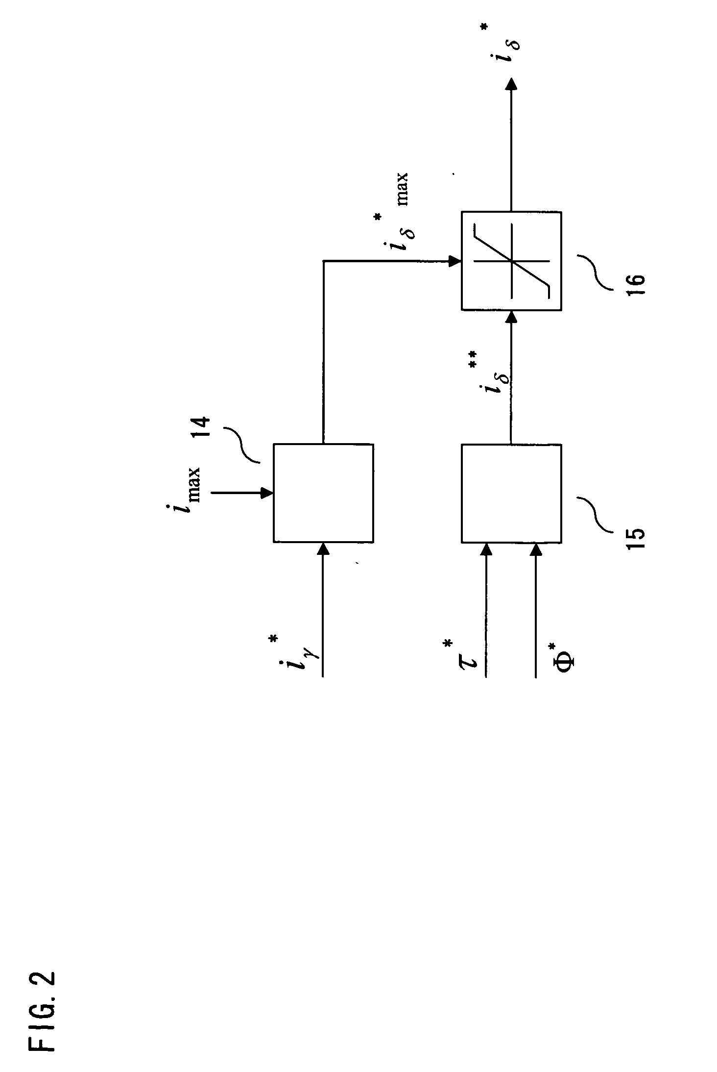
[0058]If the inductance of the synchronous machine 1 is large, however, there may arise a case where it is necessary to limit the torque command τ* for matching the interlinked armature flux Φ with the flux command Φ*. FIG. 10 is a diagram showing an internal configuration of a torque current command generator 9 employed when such torque limitations are necessary. Referring to this Figure, a torque limit generator 32 outputs a maximum torque τ*max which can be generated with magnetic flux specified by the flux command Φ* with reference to the flux command Φ*, and a limiter 33 outputs a limited torque command τ* by limiting the original torque command τ* to the maximum torque τ*max. A torque current limit generator 14, a torque current calculator...
PUM
 Abstract
Description
Claims
Application Information