Premix Burner With Mixing Section

Inactive Publication Date: 2007-11-08
ANSALDO ENERGIA SWITZERLAND AG
View PDF35 Cites 51 Cited by
  • Summary
  • Abstract
  • Description
  • Claims
  • Application Information

AI Technical Summary

Benefits of technology

[0021] With the measures according to principles of the present invention, compared with the fuel feed practiced up to now, solely from the center of the burner by means of a fuel nozzle which is arranged in the region of the swirl generator and is positioned in the smallest cross section of flow of the swirl generator, the mass flows of the fuel fed to the burner can be adapted for optimizing the burner flow zone. It is thus necessary in particular during the operation of gas turbine plants to adapt the combustion process to the respective load point of the gas turbine plant, i.e., the addition of fuel is to be appropriately selected both via the central fuel nozzle orient

Problems solved by technology

However, on account of the increasing swirl in the direction of flow inside the swirl space, the swirl flow becomes unstable and turns into an annular swirl flow having a backflow zone in the flow core.
However, the provision of a mixing tube inevitably reduces the size of the backflow bubble, especially since the swirl of the flow is to be selected in such a way that the flow does not break down inside the mixing tube.
The swirl is consequently too small at the end of the mixing tube for a large backflow bubble to be able to form.
Even tests for enlarging the backflow bubble in which the inner contour of the mixing tube provides a diffuser angle opening in a divergent manner in the direction of flow showed that such measures lead to the upstream drifting of the flame.
Furthermore, additional problems arise with regard to flow separations close to the wall along the mixing tube, these flow separations having an adverse effect on the intermixing of the fuel/air mixture.
Thus, a rich fuel/air mixture forming along

Method used


Image

  • Premix Burner With Mixing Section
  • Premix Burner With Mixing Section
  • Premix Burner With Mixing Section

Examples


Example

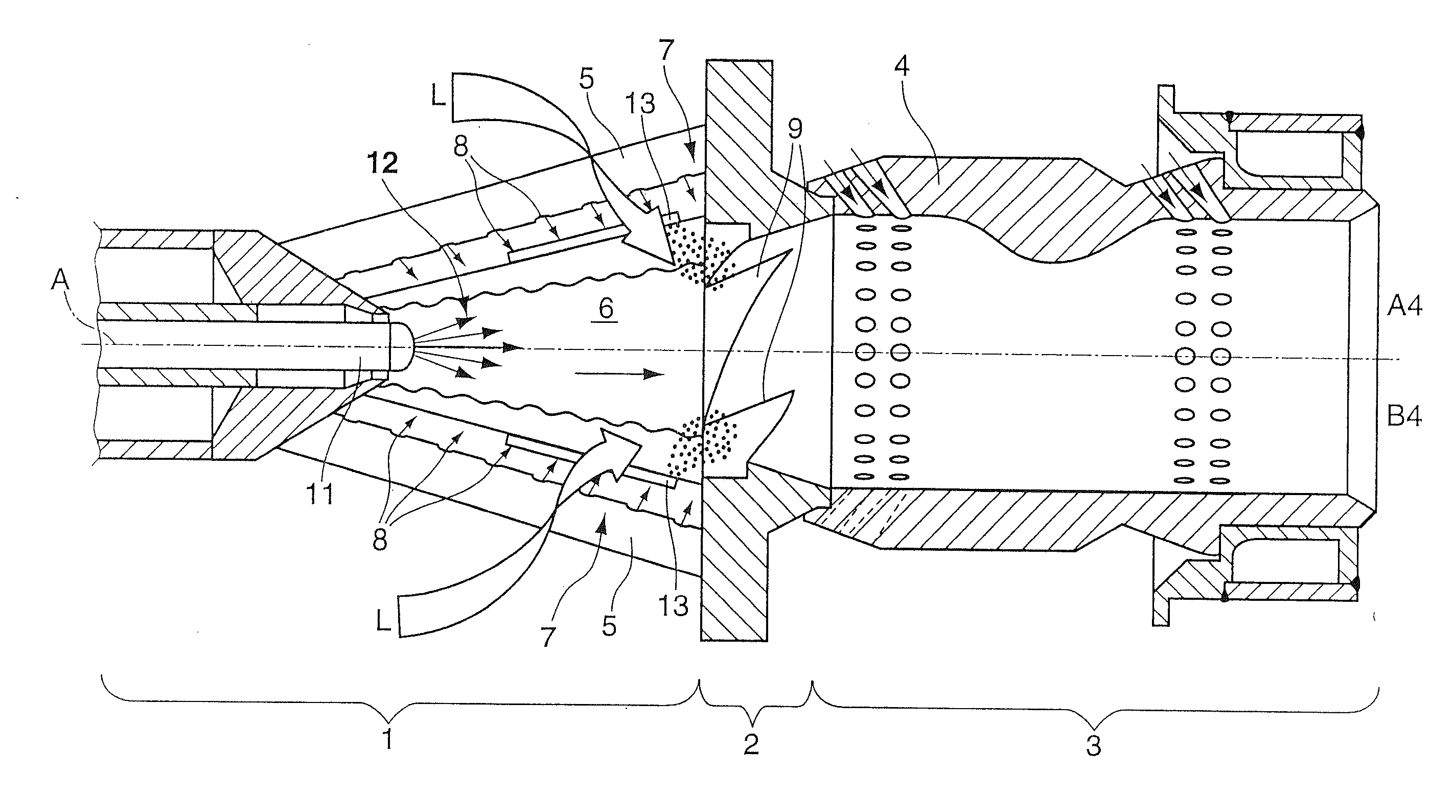
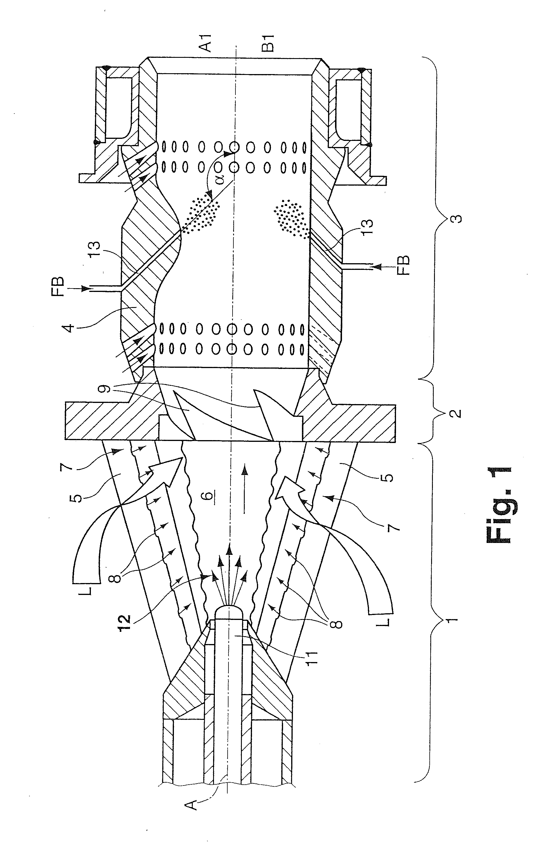
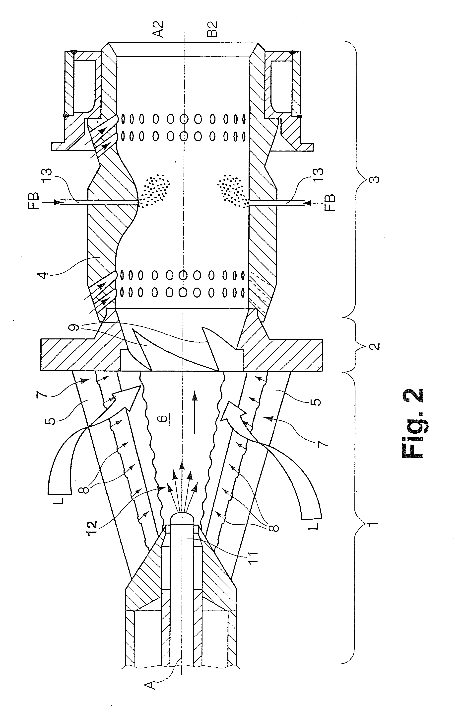
[0027] FIGS. 1 to 4 show longitudinal cross sections through a burner arrangement having a conically designed premix burner 1, adjoining which downstream along the burner axis A is a transition piece 2, which in turn is connected downstream to a mixing section 3. Not shown in the FIGS. 1 to 4 is a combustion chamber which is to be provided downstream of the mixing section 3 and serves to drive a gas turbine plant.

[0028] The premix burner 1 shown in the respective FIGS. 1 to 4 is designed as a double cone burner known per se and defines with two sectional conical shells 5 a swirl space 6 widening conically along the burner axis A in the direction of flow (see arrow illustration). In the region of the smallest internal cross section of the conically widening swirl space 6, a central liquid-fuel nozzle 11 is provided axially relative to the burner axis A, this liquid-fuel nozzle 11 forming a fuel spray 12 spreading largely symmetrically to the burner axis A. Through air-inlet slots 7 ...


PUM


Abstract

A premix burner has a mixing section (3) for a heat generator, sectional conical shells (5) which complement one another to form a swirl body, enclose a conically widening swirl space (6), and mutually define tangential air-inlet slots (7), along which feeds (8) for gaseous fuel are provided in a distributed manner, having at least one fuel feed (11) for liquid fuel, this fuel feed (11) being arranged along a burner axis (A) passing centrally through the swirl space (6), and having a mixing tube (4) adjoining the swirl body downstream via a transition piece (2). At least one additional fuel feed (13) for liquid fuel is provided in the region of the swirl body, the transition piece (2), and/or the mixing tube (4).

Description

[0001] This application is a Continuation of, and claims priority under 35 U.S.C. § 120 to, International application number PCT / EP2005 / 056168, filed 23 Nov. 2005, and claims priority therethrough under 35 U.S.C. § 119 to Swiss application number 02145 / 04, filed 23 Dec. 2004, the entireties of both of which are incorporated by reference herein.BACKGROUND [0002] 1. Field of Endeavor [0003] The invention relates to a premix burner having a mixing section for a heat generator, preferably for a combustion chamber for operating a gas turbine plant, having sectional conical shells which complement one another to form a swirl body, enclose a conically widening swirl space and mutually define tangential air-inlet slots, along which feeds for gaseous fuel are provided in a distributed manner, having at least one fuel feed for liquid fuel, this fuel feed being arranged along a burner axis passing centrally through the swirl space, and having a mixing tube adjoining the swirl body downstream v...

Claims


Application Information

Patent Timeline
IPC IPC(8): F23C5/00F23M3/00F23C7/00F23M3/04
CPCF23C2201/20F23R3/286F23D17/002F23C2900/07002
Inventor KNOEPFEL, HANS PETER
Owner ANSALDO ENERGIA SWITZERLAND AG
Why Eureka
Try Eureka