Non-snag polymer ligating clip

a polymer and ligating clip technology, applied in the field of surgical clips, can solve the problems of limited space and visibility, time-consuming and difficult to perform complex manipulations of surgical threads, and the use of surgical threads for ligation requires complex needle manipulations, etc., and achieve the effect of removing the clip

Inactive Publication Date: 2007-05-24
TELEFLEX MEDICAL INC
View PDF24 Cites 206 Cited by
  • Summary
  • Abstract
  • Description
  • Claims
  • Application Information

AI Technical Summary

Benefits of technology

[0010] In accordance with the present disclosure, a polymeric surgical clip is provided of the type comprising first and second legs joined at their proximal ends by a flexible hinge section. Each leg has a vessel clamping inner surface, an opposite outer surface, and a pair of opposing side surfaces. The vessel clamping inner surface is in opposition to the vessel clamping inner surface of the other leg. Further, a female locking member is positioned on the distal end of the first leg and a male locking member is positioned on the distal end of the second leg. The female and male locking members are formed such that when the first and second leg members are moved from an open position to a closed position about the hinge section, the male locking member is lockingly engaged in the female locking member so as to removably lock the clip in the closed position.
[0014] In another embodiment of the non-snag polymer ligating clip, a first protuberance is located on the outer surface of the first leg between the hinge section and the distal end of the first leg, and a second protuberance is located on the outer surface of the second leg adjacent the distal end of the second leg such that the first and second protuberances serve to allow for engagement and application of the surgical clip by a clip applier apparatus.
[0015] In still another embodiment of the non-snag polymer ligating clip of the discovery, a first pair of arcuate protuberances are joined to opposite sides of the first leg between the hinge section and the distal end of the first leg, and a second pair of arcuate protuberances are joined to opposite sides of the second leg adjacent the distal end of the second leg such that the first and second pair of arcuate protuberances serve to allow for engagement and application of the surgical clip by a clip applier apparatus.
[0016] The non-snag polymeric surgical clip disclosed herein is most suitably made of polymeric material and accordingly minimizes interference with high technology diagnostic modalities such as CATSCAN, MRI and MRS. At the same time, the clip is nearly as small as comparable metal clips while maintaining sufficient strength and possessing a high degree of security in the clip's latching mechanism. The ligating clip of the discovery is further configured with low profile bosses used for engagement and application by a clip applier apparatus, and wherein the low profile bosses will facilitate introduction into tight spaces during coronary artery bypass graft procedures and very importantly is less prone to snag a suture during coronary artery bypass graft surgical procedures than a conventional polymeric ligating clip having conventional bosses at the end of both the first and second leg that extend outwardly from the side surfaces thereof.

Problems solved by technology

The use of surgical thread for ligation requires complex manipulations of the needle and suture material to form the knots required to secure the vessel.
Such complex manipulations are time-consuming and difficult to perform, particularly in endoscopic surgical procedures, which are characterized by limited space and visibility.
With the advent of high technology diagnostic techniques using computer tomography (CATSCAN or CT) and magnetic resonance imaging (MRI), metallic clips have been found to interfere with the imaging techniques.
Unlike metallic clips, which are usually symmetric, polymeric clips are usually asymmetric in design and hence lack an axis of symmetry.
However, metal clips are not viable when there is a desire to use a CT scan to study the patency of a graft after bypass surgery.
Thus, there is a long-felt need in coronary artery bypass surgery to find an alternative to the metal ligating clip used to tie off branches of the IMA being used for a coronary artery bypass graft since the metal ligating clips do not readily lend themselves to CT scans to study the patency of a graft after a bypass.

Method used


Image

  • Non-snag polymer ligating clip
  • Non-snag polymer ligating clip
  • Non-snag polymer ligating clip

Examples


Embodiment Construction

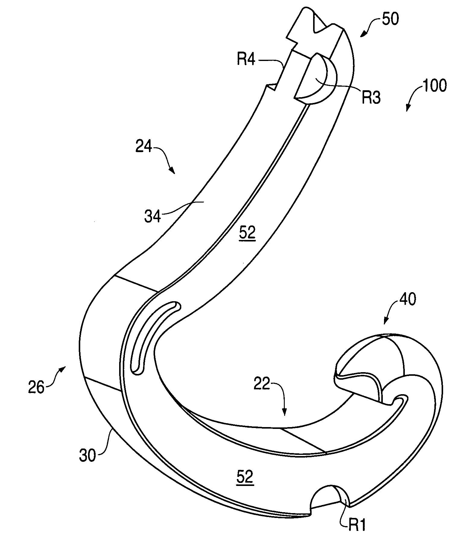
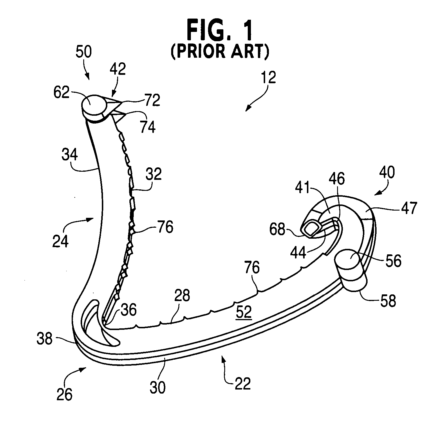
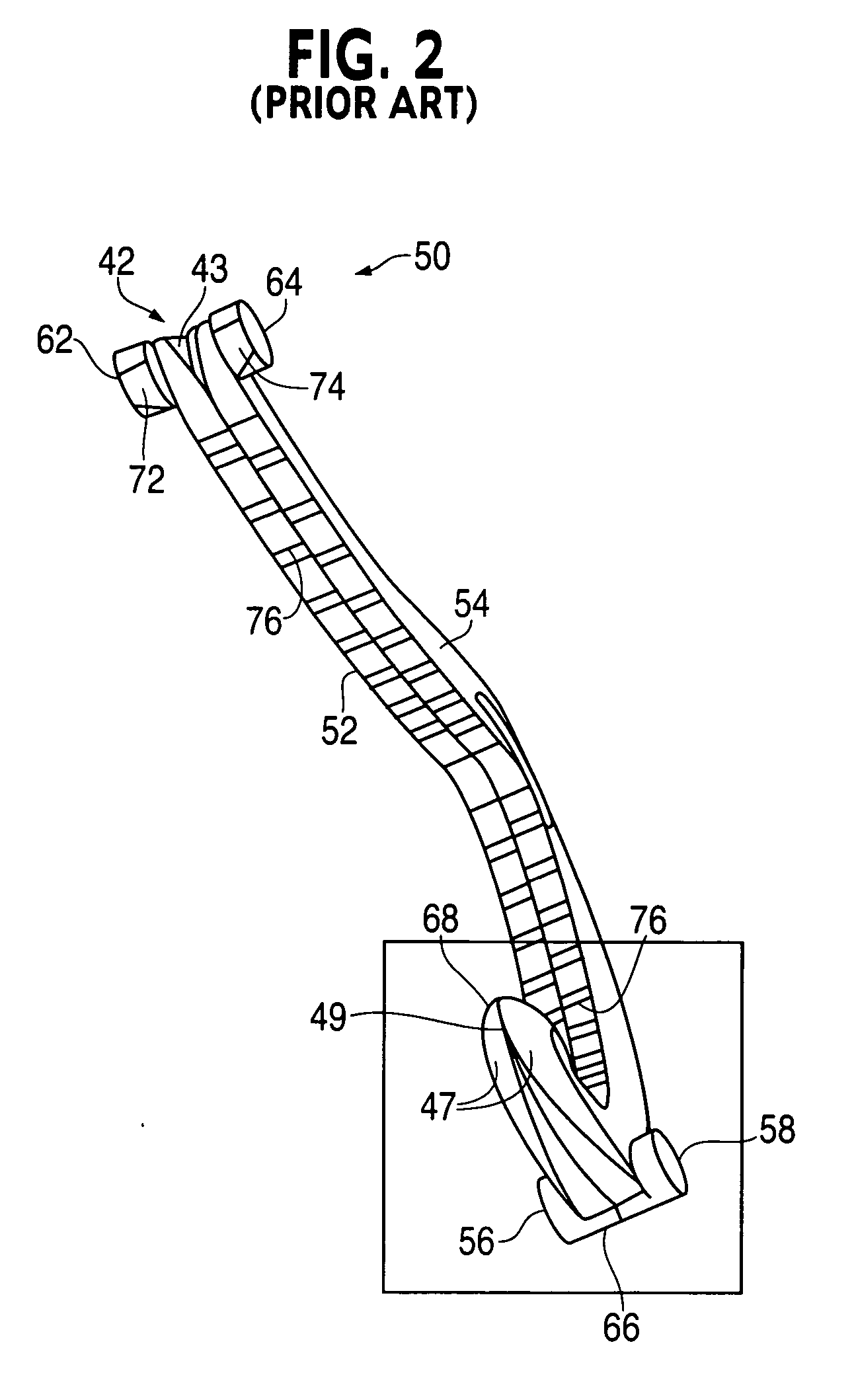
[0028] Referring first to FIGS. 1-2 of the drawings, one example is illustrated of a conventional asymmetric surgical clip 12. Clip 12 and others of similar design are particularly useful as hemostatic clips that can be latched around a vessel or other type of tissue to ligate the vessel and thereby stop or reduce the flow of fluid through the vessel. Clip 12 can be constructed from any suitable biocompatible material. However, the presently disclosed subject matter is particularly suitable for practice with polymeric clips. Thus, clip 12 preferably comprises a one-piece integral polymeric body formed from a suitable strong biocompatible engineering plastic such as the type commonly used for surgical implants. Examples include, but are not limited to, acetyl polyoxym ethylene (POM), polyethylene terephthalate (PET), polybutylene terephthalate (PBT), polyoxymethylene, or other thermoplastic materials having similar properties that can be injection-molded, extruded or otherwise proces...


PUM


Abstract

A polymeric, surgical clip having first and second curved legs with each having a pair of opposing side surfaces joined at their proximal ends by a flexible hinge section and movable from an open position to a closed position for clamping a vessel between curved opposing inner surfaces. The first leg terminates at its distal end in a female locking member, and the second leg member terminates in a male locking member complimentary to the female locking member such that when the first and second leg members are moved from an open position to a closed position about the hinge section the male member is lockingly engaged in the female locking member. The clip is provided with low profile boss-like elements on the legs thereof to reduce the risk of snagging a suture during coronary artery bypass graft surgery.

Description

TECHNICAL FIELD [0001] The present invention relates to surgical clips, and more particularly to a non-snag polymer ligating clip which is easier to introduce into tight spaces during coronary artery bypass graft surgery and which is less prone to catch a suture when attaching a graft IMA (internal mammary artery) to the coronary artery during the coronary artery bypass graft procedure. More particularly, the present disclosure relates to an improved surgical ligating clip that can be used in coronary artery bypass graft surgical procedures without catching a suture during attachment of a graft IMA to the coronary artery and which subsequently allows for CT (computer tomography) to check patency in the coronary artery bypass graft juncture since the clip is translucent and not visible on CT. BACKGROUND ART [0002] Many surgical procedures require vessels or other tissues of the human body to be ligated during the surgical process. For example, many surgical procedures require cutting...

Claims


Application Information

Patent Timeline
Patent Type & Authority Applications(United States)
IPC IPC(8): A61B17/08
CPCA61B17/122A61B17/1227
Inventor KENNEDY, DANIEL L.WILSON, DONALD F. JR.KNODEL, BRYAND
Owner TELEFLEX MEDICAL INC
Why Eureka
Try Eureka