Signal processing object

a technology of signal processing and object, applied in the field of computing, to achieve the effect of reducing power consumption, reducing power consumption, and increasing speed

Inactive Publication Date: 2006-02-02
SCHLERETH FREDERICK H
View PDF3 Cites 5 Cited by
  • Summary
  • Abstract
  • Description
  • Claims
  • Application Information

AI Technical Summary

Benefits of technology

[0009] The present invention is directed to a novel DSP referred to herein as a Signal Processing Object (SPO). An SPO is a digital signal processing circuit that is an alternative to traditio...

Problems solved by technology

Verifiability is important as ...

Method used


Image

  • Signal processing object
  • Signal processing object
  • Signal processing object

Examples


Embodiment Construction

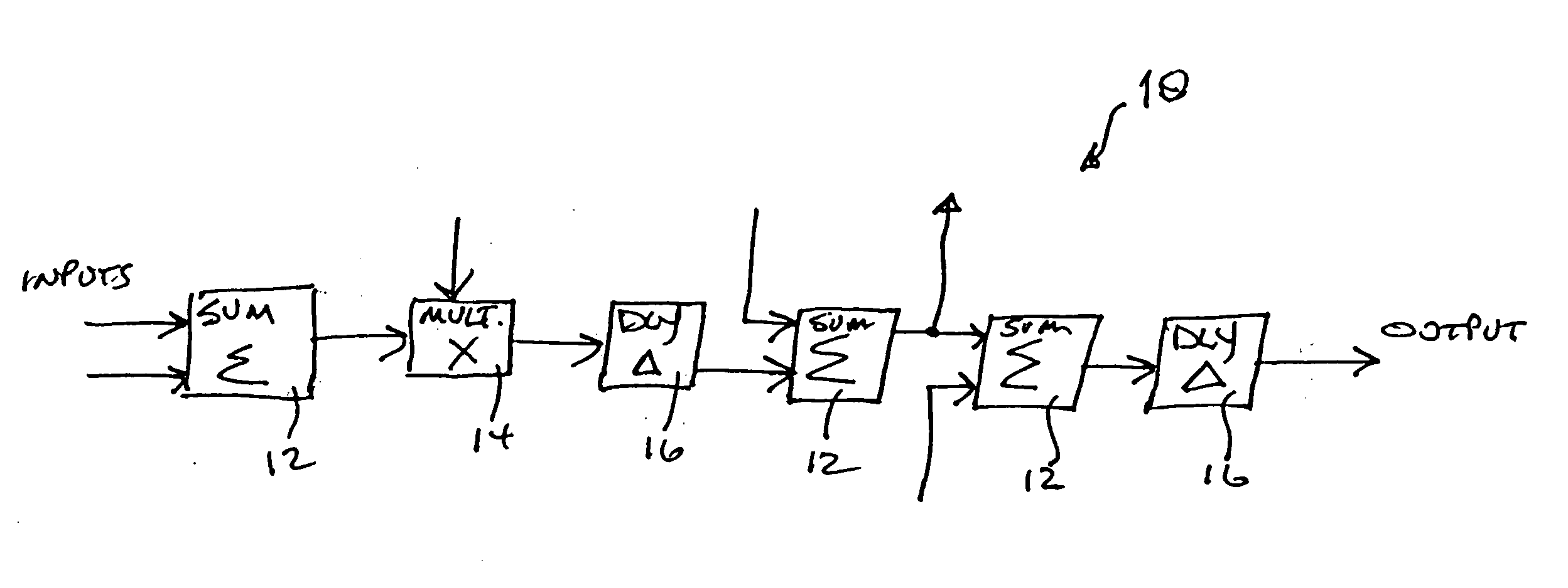
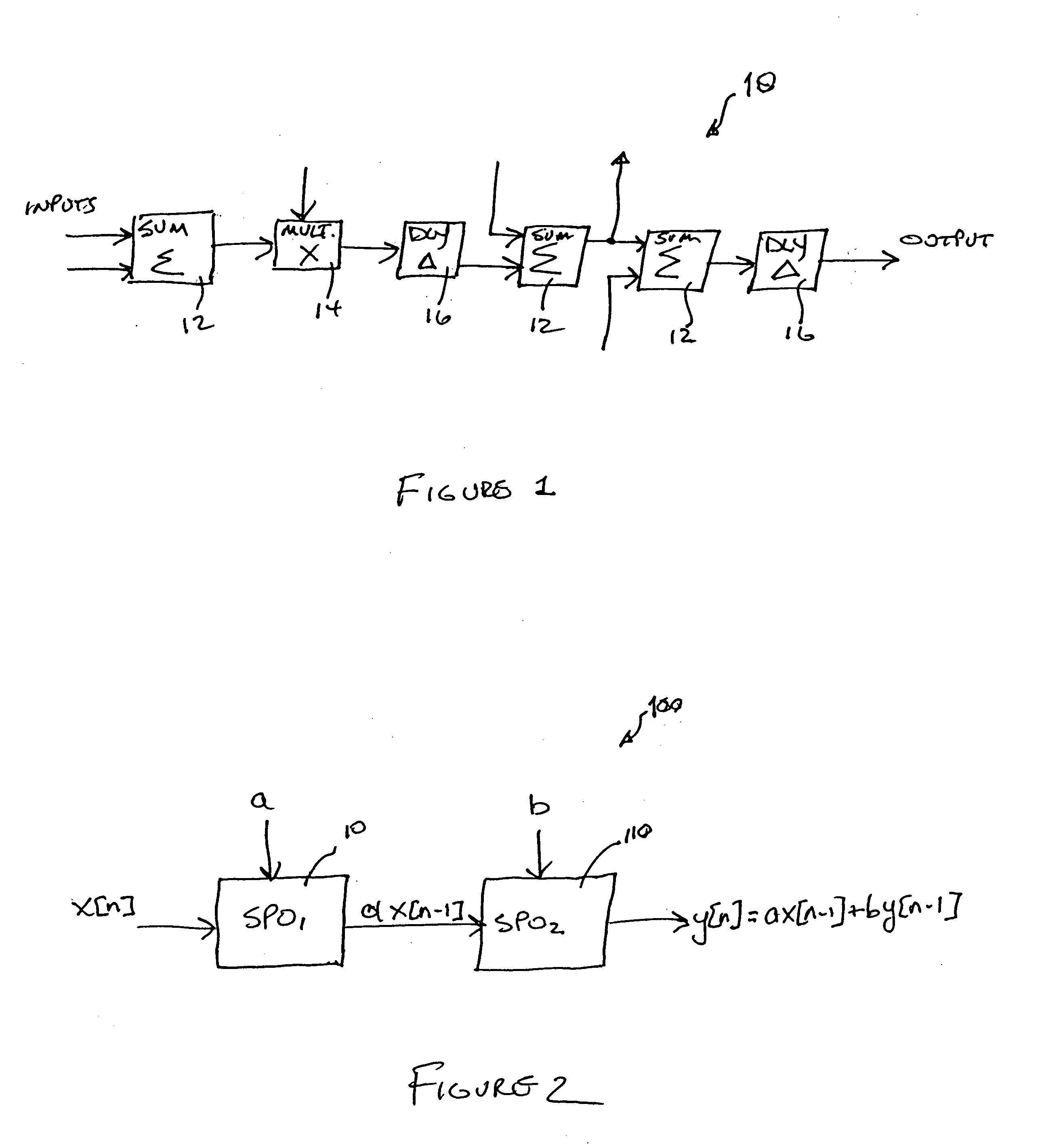
[0031] Reference will now be made in detail to the present exemplary embodiments of the invention, examples of which are illustrated in the accompanying drawings. Wherever possible, the same reference numbers will be used throughout the drawings to refer to the same or like parts. An exemplary embodiment of the signal processing object of the present invention is shown in FIG. 1, and is designated generally throughout by reference numeral 10.

[0032] As embodied herein and depicted in FIG. 1, a block diagram of a signal processing object (SPO) in accordance with an embodiment of the present invention is disclosed. It will be apparent to those of ordinary skill in the pertinent art that modifications and variations can be made to SPO 10 of the present invention depending on whether the present invention is implemented in software or hardware. For example, if the invention is implemented in hardware, SPO 10 may be implemented in an ASIC, FPGA or custom integrated circuit. SPO 10 of the...


PUM


Abstract

The present invention is a digital signal processing object that includes at least one summer element and at least one delay register connected to the at least one summer element. The combination of the at least one summer element and the at least one delay register is arranged and configured to solve a term of a difference equation. The digital signal is processed as an independent variable in the difference equation.

Description

CROSS-REFERENCE TO RELATED APPLICATIONS [0001] This Application claims priority under 35 U.S.C. §119(e) based on U.S. Provisional Patent Application Ser. No. 60 / 591,331 filed Jul. 27, 2004, the contents of which are relied upon and incorporated herein by reference in their entirety.BACKGROUND OF THE INVENTION [0002] 1. Field of the Invention [0003] The present invention relates generally to computing, and particularly to digital signal processing. [0004] 2. Technical Background [0005] Digital Signal Processing (DSP) is an area of computer science that processes signals that typically represent physical phenomena obtained from one or more sensors. DSP has a wide variety of applications and its importance is evident in such fields as pattern recognition, radio communications, telecommunications, radar, biomedical engineering, and as well as many others. For example, the digital signals may represent RF data, seismic vibrations, video or other visual images, sound waves, and etc. By de...

Claims


Application Information

Patent Timeline
IPC IPC(8): G06F1/26G06F1/30
CPCG06F1/32
Inventor SCHLERETH, FREDERICK H.
Owner SCHLERETH FREDERICK H
Why Eureka
Try Eureka