Method and apparatus for positioning a billiard game rack

Inactive Publication Date: 2006-03-02
MCGRAIL PETER +1
View PDF16 Cites 20 Cited by
  • Summary
  • Abstract
  • Description
  • Claims
  • Application Information

AI Technical Summary

Benefits of technology

[0005] It is an object to the present invention to provide a method and apparatus that will facilitate simultaneous preci

Problems solved by technology

The reliance on positioning the apex ball on the foot spot has inherent weaknesses.
For example, when the apex ball is on top of the foot spot it is not possible to see the foot spot.
While the apparatus described therein provides some advantage over the mere reliance on a foot spot on the upper face of the table, it still does not ensure the precise placement of all of the other balls within the rack.
The placemen

Method used


Image

  • Method and apparatus for positioning a billiard game rack
  • Method and apparatus for positioning a billiard game rack
  • Method and apparatus for positioning a billiard game rack

Examples


Example

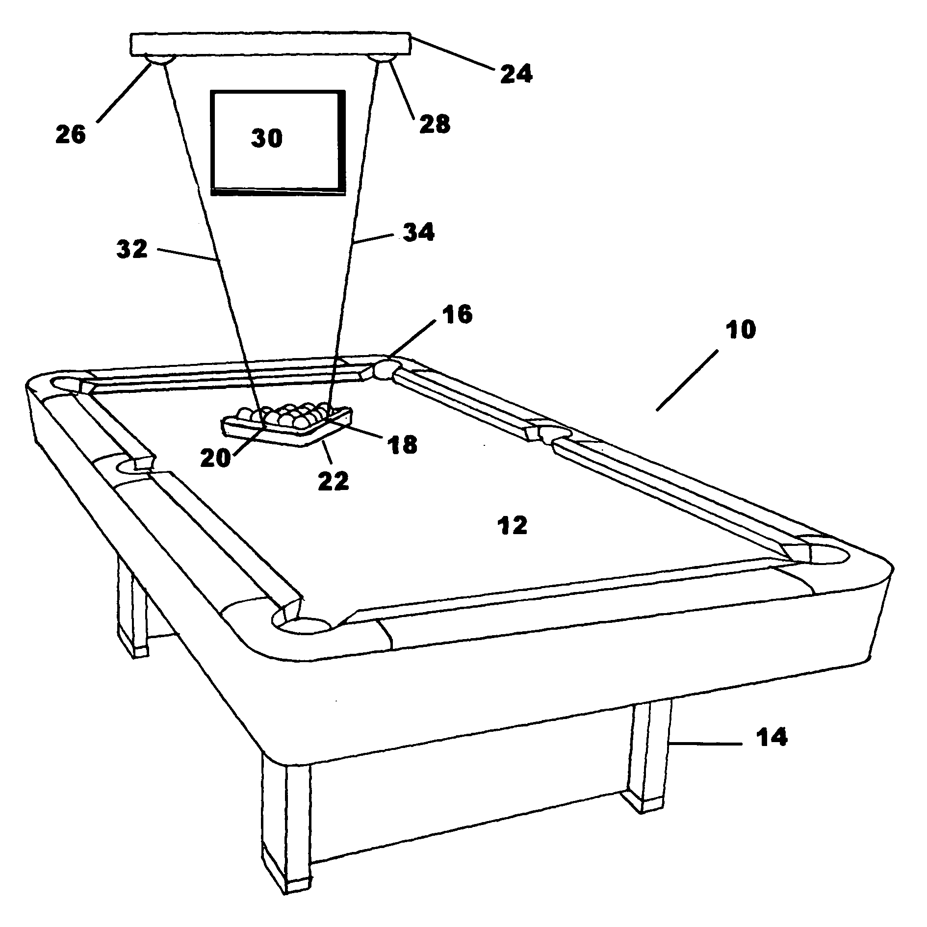
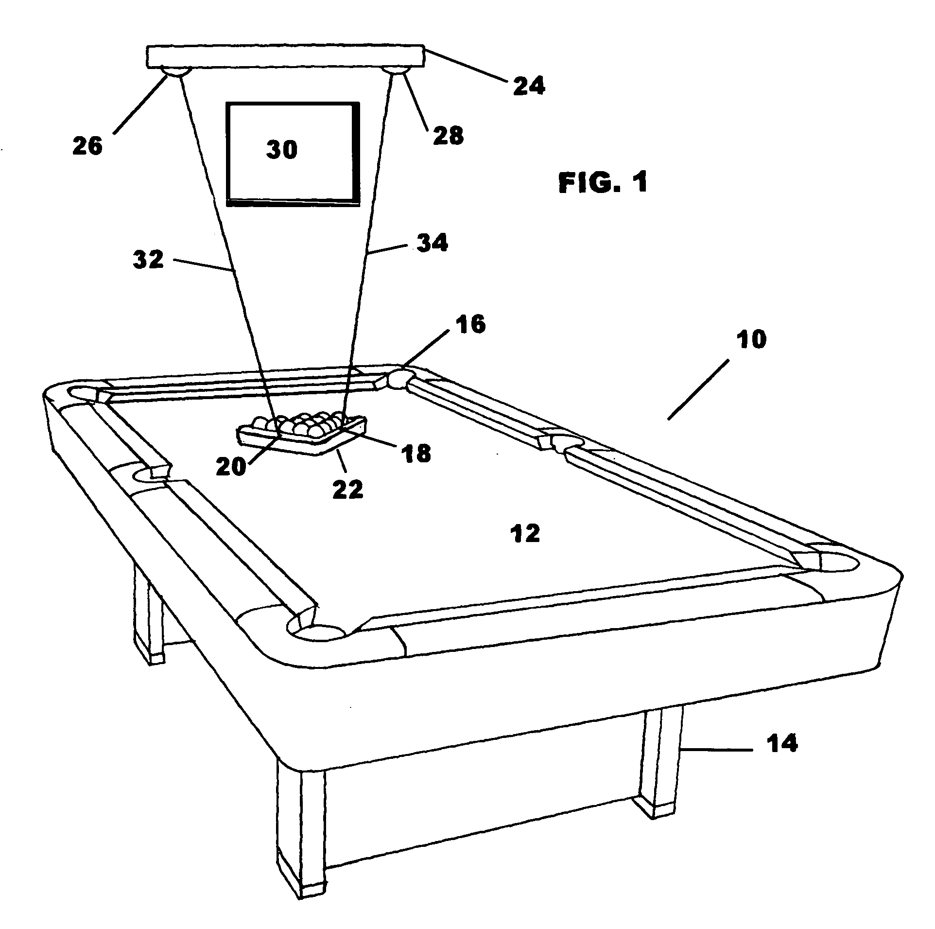
[0021] Referring now to FIG. 1 there is shown one form of the apparatus in accordance with the present invention. The apparatus 10 includes a conventional billiard table 12 having a base 14. The table 12 has an elongated rectangular shape in accordance with the customary design. Pockets 16 are disposed at each corner and at the midpoints of the longer sides thereof. The balls other than the cue ball are racked in a rack 22 having indicia 18, 20 disposed on the upper face thereof. In the preferred embodiment the indicia or spots 18, 20 are disposed symmetrically. Thus, the respective distances between each indicia 18, 20 and the apex of the rack 22, adjacent to the apex ball, are equal.

[0022] Illustrated diagrammatically is the overhead elongated lighting apparatus 30. This apparatus typically extends over a substantial axial part of the table 12 to ensure that the players have adequate illumination. It is the lighting apparatus 30 that is an obstacle to retrofitting existing billia...


PUM


Abstract

Apparatus for cooperation with an associated billiard table which includes first and second laser apparatus for producing respective first and second laser spots, a rack for positioning a plurality of balls confined within said rack. The rack has first and second indicia thereon and a support carrying said first and second laser apparatus in spaced relationship. The support may be dimensioned and configured to permit adjustment thereof to align respectively said first and second laser spots with respectively said first and second indicia when said rack is in a predetermined location on the associated billiard table. Some forms of the apparatus include at least one ball and socket joint for supporting at least one of the first and second laser apparatus. Other forms of the apparatus include a support that includes first and second socket joints for respectively supporting said first and second laser apparatus. The rack may be triangular and the first and second indicia may be positioned on first and second sides of the rack and said first and second sides of the rack may be adjacent. In some forms of the invention first and second sides of the rack intersect in a first apex that is proximate to the apex ball when the balls are racked. The first and second indicia may be disposed at equal distances from an apex. Various forms of the method include the step of providing adjustable structure that includes providing at least one ball and socket joint. Other forms include the step of providing a rack includes providing a rack that that is triangular and has first and second indicia on first and second sides of the rack and said first and second sides of said rack are adjacent. The method may include a step of providing a rack that has first and second sides of the rack that intersect in a first apex that is proximate to the apex ball when balls are racked within the rack. The method may include the step of providing a rack that has the first and second indicia disposed at equal distances from the first apex.

Description

BACKGROUND OF THE INVENTION [0001] The invention relates to pocket billiards apparatus and methods and particularly to apparatus and methods for positioning the ball rack used to position the balls to start a new game. The term “billiards” as used herein will be understood to refer to the games of billiards, pool, and snooker. More particularly, the rack positions all of the balls, except the cue ball, in an array appropriate for the specific game. For example, the array may be triangular although other games may utilized in array having another shape. For those games utilizing a triangular array, the rack must be positioned so that the ball at the apex of the triangular array nearest to the center of the table is directly on the foot spot. When the balls are racked, all the balls in the array must be lined up behind the apex ball (when present) and pressed together so that adjacent balls are in contact with each other. The positioning of the balls in the racking process affects the...

Claims


Application Information

Patent Timeline
IPC IPC(8): G01C15/00
CPCY10S33/21A63D15/005
Inventor MCGRAIL, PETERCOUTURE, KEN
Owner MCGRAIL PETER
Why Eureka
Try Eureka