Loading plate structure for embedded burying semiconductor chip

A carrier board and semiconductor technology, applied in semiconductor devices, semiconductor/solid-state device parts, electric solid-state devices, etc., can solve problems such as damage to semiconductor chips, uneven filling of adhesive materials, excessive stress on the periphery of semiconductor chips and the periphery of openings, etc.

Inactive Publication Date: 2008-10-08
PHOENIX PRECISION TECH CORP
View PDF0 Cites 1 Cited by
  • Summary
  • Abstract
  • Description
  • Claims
  • Application Information

AI Technical Summary

Problems solved by technology

However, the manufacturing process of the above-mentioned prior art is to form vertical openings with the same upper and lower dimensions in the carrier board, which is not conducive to placing the semiconductor chip in the opening of the carrier board.
[0008] In addition, the manufacturing process of the above-mentioned prior art is to directly fill the opening with the adhesive material. Since the gap between the semiconductor chip and the opening is a narrow straight slit, when the adhesive material is injected into the slit, it is easy to make the opening 100 fail. It is completely filled with the adhesive material, which makes the adhesive material in the opening unevenly filled, and it is easy to leave air, which will cause the explosion phenomenon in the subsequent thermal cycle process, which seriously affects the reliability of the subsequent process.
[0009] And, in the manufacturing process of the prior art, vertical openings with the same upper and lower dimensions are formed in the carrier board. Due to the different thermal expansion coefficients, when the semiconductor chip is placed in the opening and undergoes a subsequent thermal cycle process to generate thermal expansion effects, the The edge of the semiconductor chip is easily damaged by the extrusion of the edge of the opening; or the peripheral edge of the active surface of the semiconductor chip and the peripheral edge of the opening are overstressed, resulting in delamination between the insulating layer used in the subsequent circuit build-up process and the peripheral edge of the opening, and then Affect the quality of embedded chips on the circuit board
[0010] Therefore, how to propose a new circuit board structure for embedding semiconductor chips, so as to avoid that the existing technology is not conducive to placing the semiconductor chip in the vertical opening of the circuit board, the glue filling is uneven, and bubbles are easy to remain, and it is easy to expand due to thermal expansion. The resulting stress damages the semiconductor chip, or the excessive stress on the periphery of the semiconductor chip and the periphery of the opening, which is not conducive to the subsequent circuit build-up process, has become a subject that the industry is eager to solve.

Method used


Image

  • Loading plate structure for embedded burying semiconductor chip
  • Loading plate structure for embedded burying semiconductor chip
  • Loading plate structure for embedded burying semiconductor chip

Examples


Embodiment Construction

[0045] The implementation of the present invention is described below through specific examples, and those skilled in the art can easily understand other advantages and effects of the present invention from the content disclosed in this specification.

[0046] Figure 3A to Figure 3E Shown is the manufacturing process of the first embodiment of the carrier board structure for embedding semiconductor chips of the present invention.

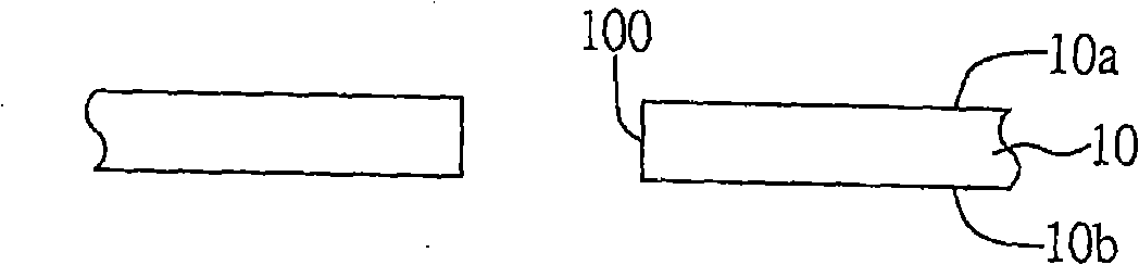
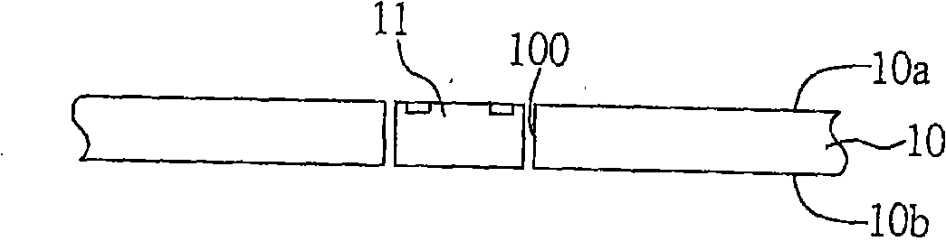
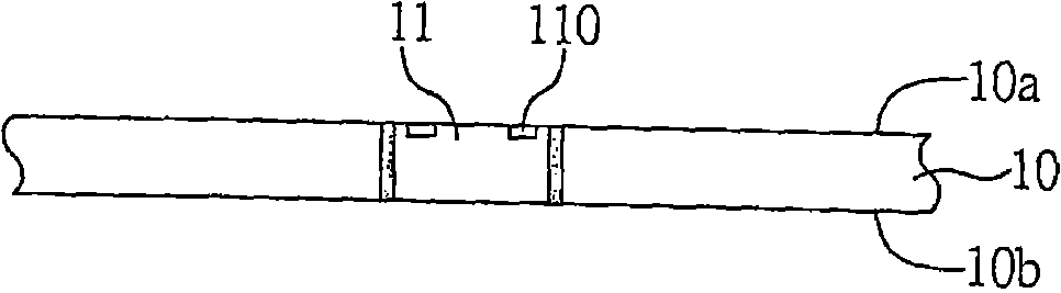
[0047] As shown in FIG. 3A , first, a carrier plate 20 having a first surface 20 a and a second surface 20 b opposite to the first surface is provided, and at least one opening 21 with a chamfer 210 is formed in the carrier plate 20 , And the opening 21 is circular or rectangular, and the opening 21 runs through the first and second surfaces 20 a and 20 b of the carrier board 20 , and the chamfer 210 is a full chamfer. In this embodiment, the opening 21 is formed by one of cutting, stamping, laser and other forming methods.

[0048] In this embod...


PUM


Abstract

The invention discloses a loading plate structure for embedding a semiconductor chip. The loading plate structure mainly includes a loading plate with a first surface and a corresponding second surface, the loading plate has at least one opening with a advance angle, the semiconductor chip is easy to arrange in the opening through the advance angle, adhesive material can be filled in the opening uniformly and enough through the advance angle, air bubble generation and stress reduction can be avoided.

Description

technical field [0001] The invention relates to a carrier board structure for embedding semiconductor chips, in particular to a structure for embedding semiconductors in the carrier board. Background technique [0002] With the evolution of semiconductor packaging technology, different packaging types have been developed for semiconductor devices, which mainly install semiconductor chips on a package substrate or lead frame first, and then electrically connect the semiconductor chips On the packaging substrate or lead frame, it is then packaged with colloid; among them, the ball grid array (Ball gridarray, BGA) is an advanced semiconductor packaging technology, which is characterized in that a packaging substrate is used to place the semiconductor chip, and the use of automatic Self-alignment technology is used to implant a plurality of solder balls arranged in a grid array on the back of the package substrate, so that more input / output terminals can be accommodated on the s...

Claims


Application Information

Patent Timeline
Patent Type & Authority Applications(China)
IPC IPC(8): H01L23/13H01L23/488H01L23/498H01L23/28H05K1/18
CPCH01L2224/04105H01L2224/19H01L2224/32225H01L2224/73267H01L2224/92244H01L2924/15153
Inventor 史朝文
Owner PHOENIX PRECISION TECH CORP
Why Eureka
Try Eureka