Method and apparatus for targeting blind holes in intramedullary rods

Inactive Publication Date: 2008-07-03
LEVIN GORDON L
View PDF2 Cites 2 Cited by
  • Summary
  • Abstract
  • Description
  • Claims
  • Application Information

AI Technical Summary

Benefits of technology

[0003]The methods and devices described below facilitate placement of intramedullary nails. A method for locating and drilling through a bone to engage the transverse blind holes in an intramedullary nail is accomplished with a radio-opaque target secured to a patient using a strap or any other suitable binding. The radio-opaque target is surrounding a drill channel or port. Iterative fluoroscope images accompanied by adjustment of the target in relation to the imbedded intramedullary nail orients the drill channel through the target with a first hole in the intramedullary nail. An incision permits the surgeon to observe the tip of a drill bit or burr inserted through the target in relation to the bone to be drilled. The first hole is drilled through the bone engaging the first transverse hole in the intramedullary nail. The radio-opaque target may be removed while leaving the drill bit in place. A drill guide may placed with a first hole engaging the first drill bit and a second hole to accept a second drill bit. The drill guide is secured to the patient using a strap, and the second drill bit is used to drill a second hole through the bone engaging the second transverse hole in the intramedullary nail.

Problems solved by technology

The conventional guide solutions suffer from flexure of the guide owing to the distance from the point of attachment to the nail, or from bending or twisting of the intramedullary nail during insertion.
These problems lead to surgeons having to “eyeball” the blind holes in the distal end of the nail which requires the surgeon to be in close proximity to the radiation while using the fluoroscopy.
This inexact procedure increases operating time, risk of multiple holes drilled into the bone weakening the structure, and increased radiation as well as frustration to the surgeons.

Method used


Image

  • Method and apparatus for targeting blind holes in intramedullary rods
  • Method and apparatus for targeting blind holes in intramedullary rods
  • Method and apparatus for targeting blind holes in intramedullary rods

Examples


Embodiment Construction

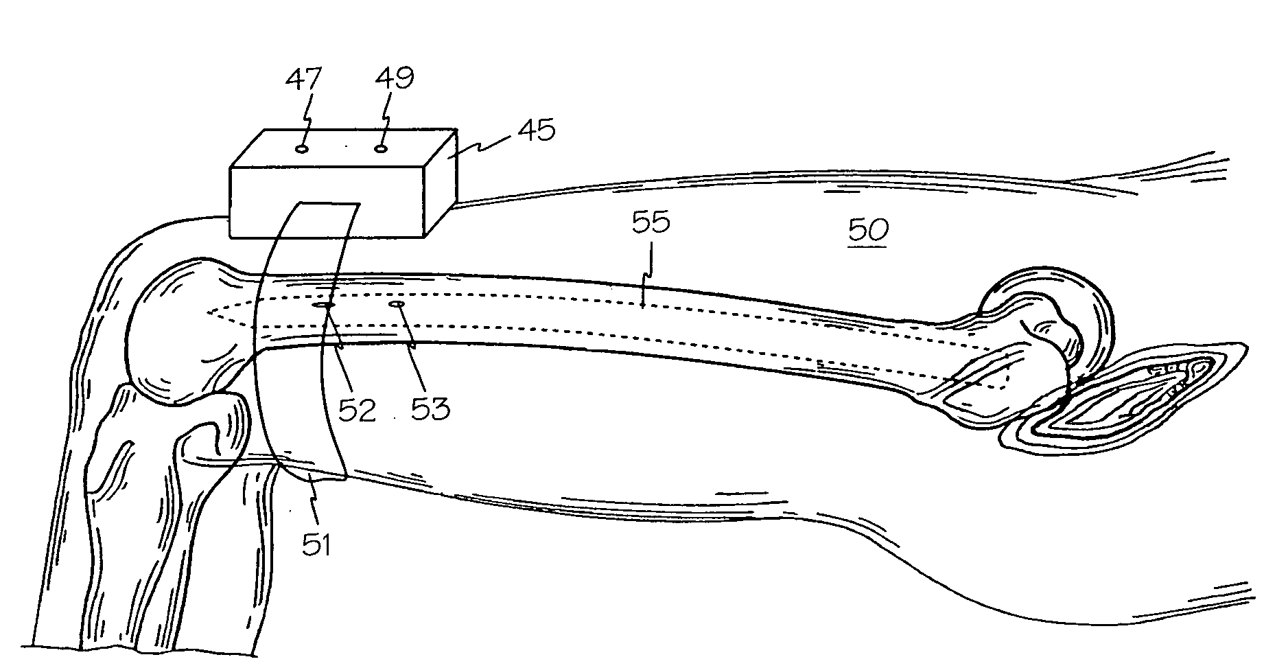
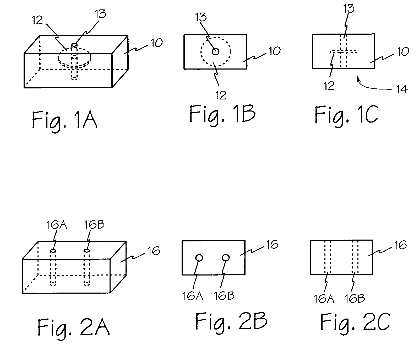
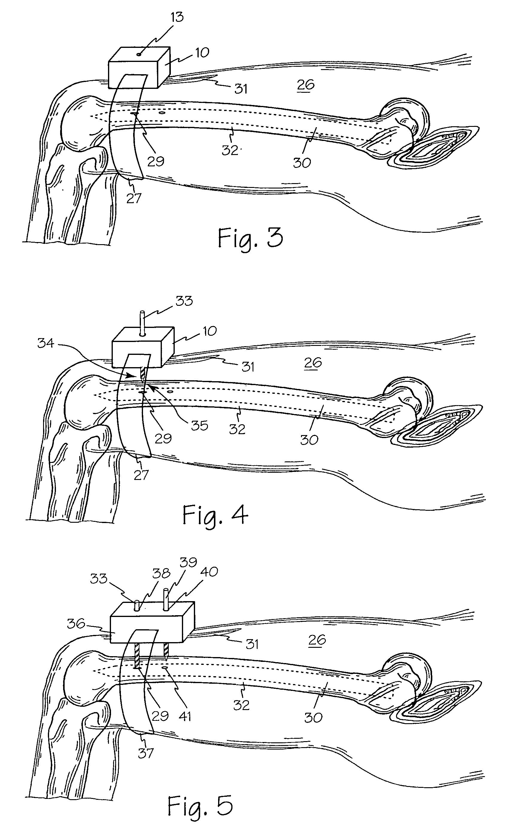
[0017]In FIGS. 1A, 1B and 1C target block 10 is illustrated with radio-opaque target 12 surrounding drill port 13. Target block 10 may be secured to a patient with bottom surface 14 against the patient's skin or tissue. Target block 10 may be secured to a patient using a strap or any other suitable technique permitting adjustment of the position to achieve proper orientation of drill port 13 with a transverse hole or holes such as first hole 52 in intramedullary nail 55 of FIG. 7.

[0018]Target block 10 may be made of any material suitably transparent to fluoroscopy and radio-opaque target 12 may have any suitable shape affording accurate alignment of drill port 13.

[0019]Referring now to FIGS. 2A, 2B and 2C, drill guide 16 includes two or more drill ports such a drill ports 16A and 16B. The relative positions and orientations of drill ports 16A and 16B should be arranged to enable drill bits inserted through the drill ports to engage the transverse holes of the intramedullary nail or ...


PUM


Abstract

A device and method for locating and drilling through a bone to engage the transverse blind holes in an intramedullary nail. The method is accomplished with a radio-opaque target secured to a patient using a strap or any other suitable binding.

Description

FIELD OF THE INVENTIONS[0001]The inventions described below relate to the field of medicine and more specifically to targeting, drilling, and engaging blind holes in intramedullary nails.BACKGROUND OF THE INVENTIONS[0002]Conventional repair of broken long bones is accomplished by placement of an intramedullary rod or nail in the intramedullary canal of the bone. Securing the nail into the bone is generally accomplished with transverse screws. Locating the transverse holes in the proximal end of the nail may be accomplished with a jig or guide secured to the proximal end of the nail or hand held guides. Locating the transverse holes in the distal end of the nail has been the subject of many proposed solutions secured to the proximal end of the intramedullary nail. The conventional guide solutions suffer from flexure of the guide owing to the distance from the point of attachment to the nail, or from bending or twisting of the intramedullary nail during insertion. These problems lead ...

Claims


Application Information

Patent Timeline
IPC IPC(8): A61B17/90
CPCA61B19/54A61B17/1725A61B90/39
Inventor LEVIN, GORDON L.
Owner LEVIN GORDON L
Why Eureka
Try Eureka