Image processing apparatus, image processing method, program, and storage medium

a composite image and compression technique technology, applied in the field of compression techniques for composite images, can solve the problems of severe image deterioration in the pdl image data portion of the composite image, and achieve the effect of avoiding image deterioration

Active Publication Date: 2006-03-02
CANON KK
View PDF6 Cites 17 Cited by
  • Summary
  • Abstract
  • Description
  • Claims
  • Application Information

AI Technical Summary

Benefits of technology

[0008] The present invention has been made in consideration of the above situation, and has as its object to avoid image deterioration caused by image compression by selecting an appropriate compression parameter(compression ratio) upon compressing a composite image generated by compositing a plurality of image data.
[0014] According to the present invention, upon compressing a composite image generated by compositing a plurality of image data, image deterioration caused by image compression can be avoided by selecting an appropriate compression parameter.

Problems solved by technology

On the other hand, upon compressing composite image obtained by compositing scanned image data and PDL image data, for example, when compression parameter for a high compression ratio is selected in image compression, severe image deterioration occurs in the PDL image data portion of the composite image.
Hence, upon compressing the composite image, it is an important issue to select an optimal compression parameter(compression ratio) in correspondence with image data to be composited in terms of image deterioration.

Method used


Image

  • Image processing apparatus, image processing method, program, and storage medium
  • Image processing apparatus, image processing method, program, and storage medium
  • Image processing apparatus, image processing method, program, and storage medium

Examples


first embodiment

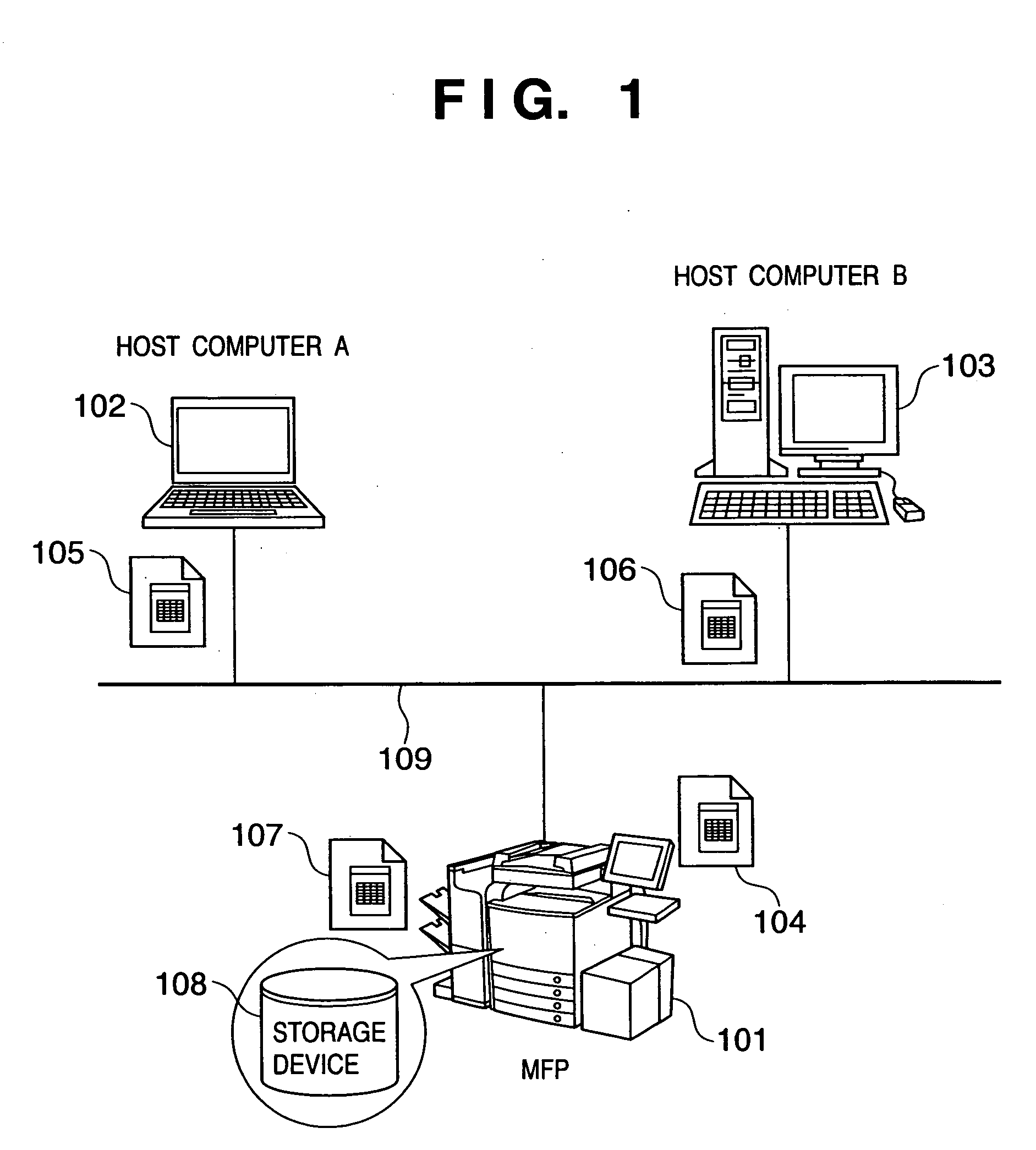
[0030]FIG. 1 is a diagram showing the overall arrangement of an image processing system which comprises an image processing apparatus (MFP 101) according to an embodiment of the present invention. Referring to FIG. 1, reference numeral 101 denotes an MFP which comprises an image composition function. Reference numerals 102 and 103 denote host computers (102: host computer A, 103: host computer B) which are connected to the MFP 101 via a network 109 to be able to communicate with each other. With this arrangement, the operation executed when the user uses the image composition function of the MFP 101 will be briefly described below.

[0031] Initially, the user registers image data 105 (PDL image data) from the host computer A or B (102, 103) in a storage device 108 in the MFP 101 as a “form image”. The user then places a original 104 on a document table of the MFP 101 and scans the original 104 by operating a control panel to obtain a “original image” (scanned image data). Assume that...

second embodiment

[0066] In the first embodiment, the compression parameter(compression ratio) is switched on the basis of the combination information 701. However, the present invention is not limited to this, and the compression parameter may be switched based on a semitransparent composition ratio in the image composition process. A detailed explanation will be given using FIGS. 9 and 10.

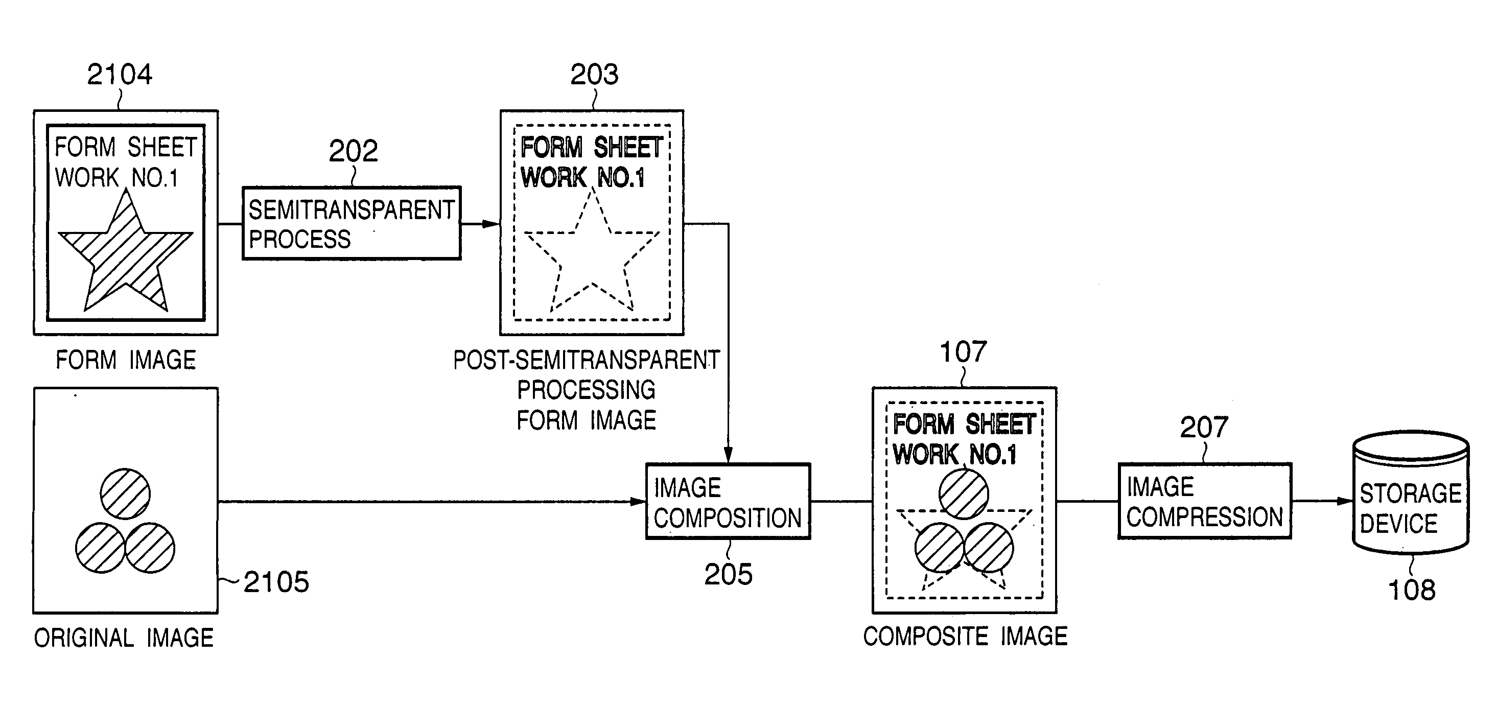
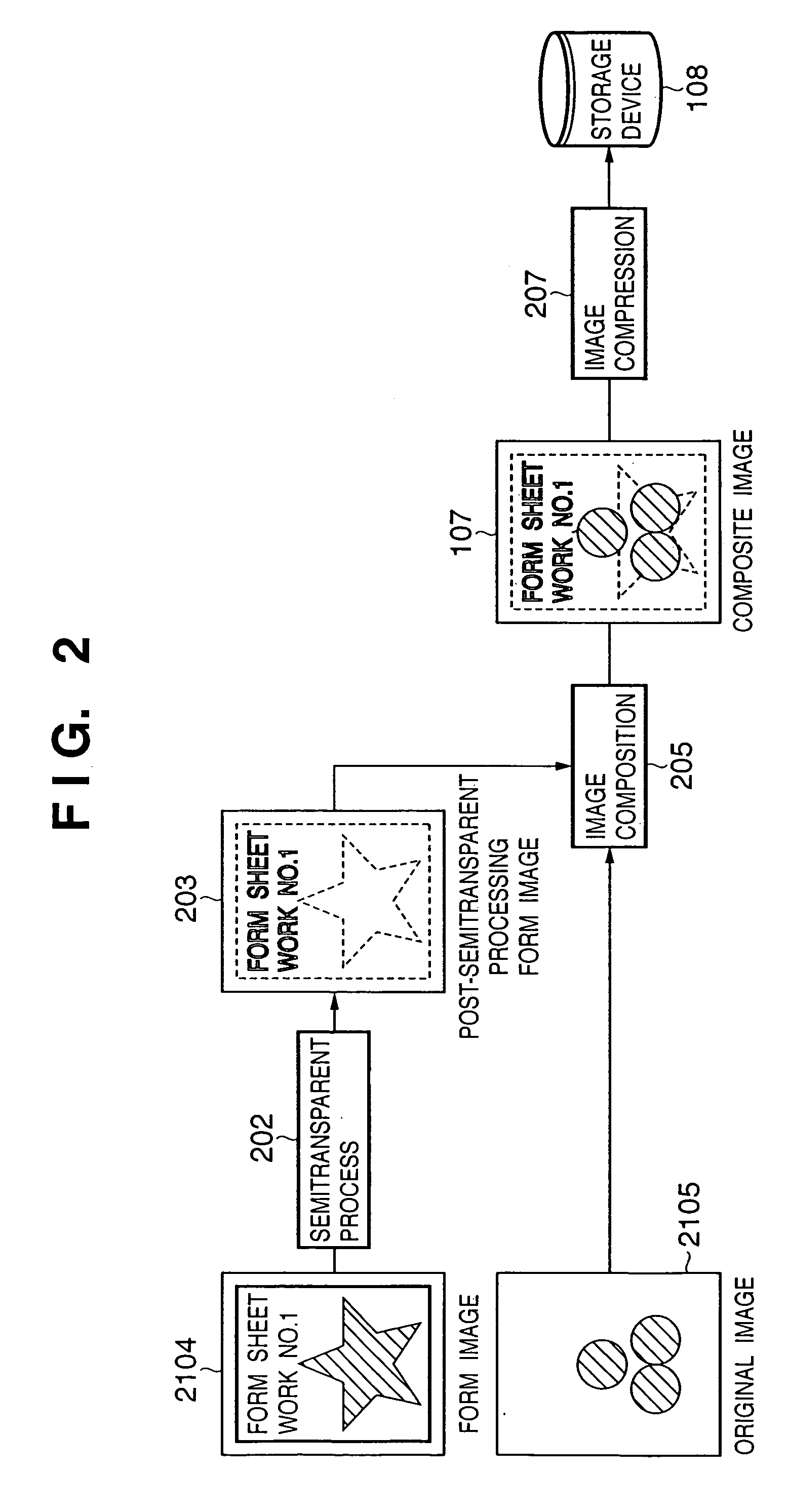
[0067]FIG. 9 is a diagram for explaining an overview of an image composition process and image compression process in the MFP according to the second embodiment of the present invention, and FIG. 10 is a flowchart showing the flow of the image composition process and image compression process.

[0068] In step S1001, the image composition unit 505 composites the post-semitransparent processing form image 203 generated by applying the semitransparent process (202) to the form image 2104, and the original image 2105 (205). In step S1002, the UI analysis unit 511 compares semitransparent composition ratio information ...

third embodiment

[0072] In the second embodiment, the compression parameter(compression ratio) is switched using the semitransparent composition ratio upon image composition. However, the present invention is not limited to this, and the compression parameter may be switched on the basis of a composite attribute flag which is generated at the same time upon image composition. A detailed explanation will be given hereinafter using FIGS. 11 and 12.

[0073]FIG. 11 is a diagram for explaining an overview of an image composition process and image compression process in the MFP according to the third embodiment of the present invention, and FIG. 12 is a flowchart showing the flow of the image composition process and image compression process.

[0074] A generation method of a composite attribute flag (form attribute flag and original attribute flag) will be described first using FIG. 11. Referring to FIG. 11, reference numeral 1101 denotes a form attribute flag as an attribute flag of the form image 2104; an...


PUM


Abstract

This invention has as its object to avoid occurrence of image deterioration caused by image compression by selecting an appropriate compression parameter upon compressing a composite image generated by compositing a plurality of image data. To this end, an image processing apparatus according to this embodiment has the following arrangement. That is, the apparatus has an image composition step (step S801) of generating a composite image by compositing a form image and original image, a checking step (steps S802 to S805) of checking for each image if each of the form image and original image to be composited is a scanned image which is generated by scanning an image by a scanner, or a PDL image which is generated via an application and is described in a page description language, a determination step (steps S806 to S809) of determining a compression parameter used to compress the composite image on the basis of a combination of the form image and original image to be composited checked in the checking step, and an image compression step (step S810) of compressing the composite image using the compression parameter determined in the determination step.

Description

FIELD OF THE INVENTION [0001] The present invention relates to a compression technique for compressing a composite image. BACKGROUND OF THE INVENTION [0002] In recent years, cases that multi-functional peripherals are equipped in offices and copy shops are increasing. A multi-functional peripheral (MFP) is an image processing apparatus which has various functions from a scan function (to be referred to as “SCAN” hereinafter) to a print function (to be referred to as “PDL” hereinafter) and a transmission function (to be referred to as “SEND” hereinafter). The MFP normally adopts a unique compression (decompression) method so as to efficiently process image data and to reduce the image memory size. [0003] More specifically, image data in “SCAN”, “PDL”, and “SEND” (scanned image data, PDL image data, and SEND image data) are compressed (decompressed) at their optimal compression parameters. For example, since the scanned image data includes many noise components of a scanner and image ...

Claims


Application Information

Patent Timeline
Patent Type & Authority Applications(United States)
IPC IPC(8): H04N1/46
CPCH04N1/387H04N19/60H04N1/41
Inventor IINUMA, OSAMUKATO, SHINICHIITO, NAOKI
Owner CANON KK
Why Eureka
Try Eureka