Fixing apparatus having a bypass transport path and image forming apparatus including the fixing apparatus

a technology of bypass transport path and fixing apparatus, which is applied in the direction of electrographic process apparatus, thin material handling, instruments, etc., can solve the problems of difficult to make a stable fixing characteristic, image deterioration, and jam, and achieve the effect of preventing heat generation

Active Publication Date: 2006-07-04
CANON KK
View PDF9 Cites 13 Cited by
  • Summary
  • Abstract
  • Description
  • Claims
  • Application Information

AI Technical Summary

Benefits of technology

[0009]It is an aspect of the present invention to provide a fixing apparatus that has a bypass transport path bypassing at least one fixing device among a plurality of fixing devices and which can prevent image deterioration, transport defects, or the like from occurring, which appear in the bypass transport path influenced by heat from a fixing device that the bypass transport path bypasses.
[0011]A fixing apparatus according to another aspect of the present invention includes two fixing devices that fix a toner image on a sheet using heat, a main transport path that transports the sheet via the two fixing devices, a bypass transport path which branches from the main transport path and transports the sheet so that the sheet bypasses one of the two fixing devices, and a heat insulator that prevents heat generated from the fixing device that the sheet transported by the bypass transport path bypasses from being transmitted to the bypass transport path.
[0012]A fixing apparatus according to another aspect of the present invention includes a plurality of fixing devices that fix a toner image on a sheet using heat, a bypass transport path that transports the sheet so that the sheet bypasses at least one fixing device among the plurality of fixing devices, a main transport path that transports the sheet via the fixing device that the sheet transported by the bypass transport path bypasses, and a heat insulator that prevents heat generated from the fixing device that the sheet transported by the bypass transport path bypasses from being transmitted to the bypass transport path.

Problems solved by technology

Kinds of a sheet material transported by an image forming apparatus have been increased year by year, and in a structure in which image fixation is performed in one fixing device, it has become difficult to make a stable fixing characteristic, good quality of a fixed image, and their productivity consistent with each other for all of these materials.
However, in a case where the bypass transport path is heated by convection heat coming from a fixing device that the bypass transport path bypasses, a problem as described below occurs.
In the case, when the bypass transport path is heated, the bypass transport path comes in contact with a sheet passing through the bypass transport path, and toner which has been fixed already on a sheet melts again, resulting in image deterioration.
Besides, the melted toner sticks to the bypass transport path, and due to this sticking toner, a jam occurs.
Further, the melted toner adheres to a transport roller provided in the bypass transport path and causes contamination on the transport path, so that a transport defect occurs or frequent service maintenance is required.

Method used


Image

  • Fixing apparatus having a bypass transport path and image forming apparatus including the fixing apparatus
  • Fixing apparatus having a bypass transport path and image forming apparatus including the fixing apparatus
  • Fixing apparatus having a bypass transport path and image forming apparatus including the fixing apparatus

Examples


first embodiment

[0027]A first embodiment of the present invention is described below.

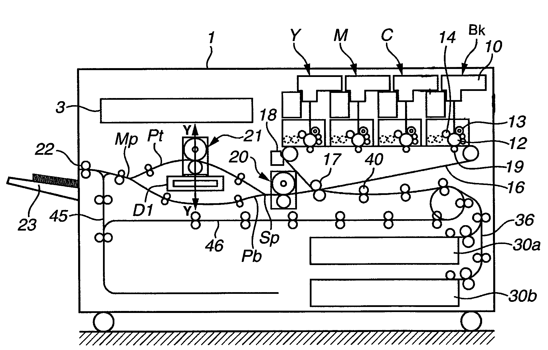
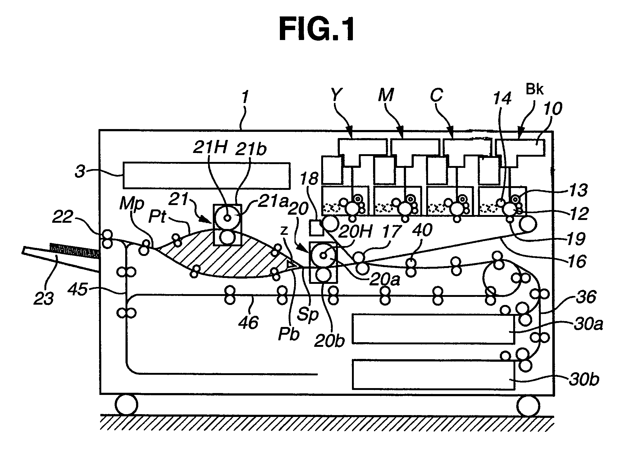
[0028]FIG. 1 is a schematic cross-sectional view of an image forming apparatus according to the first embodiment of the present invention.

[0029]FIG. 1 shows a printer main body 1. Primary image forming sections Y, M, C, and BK for forming primary images of respective yellow, magenta, cyan, and black colors are arranged in an upper part of the printer main body 1. Print data transmitted from external equipment such as a personal computer is received in a controller 3 controlling the printer main body 1 and is output to laser scanners 10 of the respective colors as image data for writing.

[0030]The laser scanners 10 emit laser beams to upper sides of photosensitive drums 12 to draw light images according to the image data for writing.

[0031]Each of the primary image forming sections Y, M, C, BK is composed of the photosensitive drum 12, a charger 13 for uniformly electrifying the surface of the photosensitive drum 12, ...

second embodiment

[0062]A structure in which a bypass passes through a portion under the second fixing device was described above with reference to the first embodiment. A second embodiment of the present invention is described below in which a bypass passes through a portion above the second fixing device.

[0063]FIG. 8 is a cross-sectional view of an image forming apparatus 1A of the second embodiment. The same reference characters are designated to members similar to those in the first embodiment, and we omit description thereof.

[0064]As shown in FIG. 8, a transport path branches at a diverging point Sp to a main path Pt2 that is a main transport path going to a second fixing device 221 and to a bypass Pb2 that is a bypass transport path which bypasses the second fixing device 221 on a downstream side of a first fixing device 220. The main path Pt2 and the bypass Pb2 merge again at a merging point Mp on a downstream side of the second fixing device 221.

[0065]The structures of the first fixing device...


PUM


Abstract

A fixing apparatus includes a plurality of fixing devices that fix a toner image on a sheet, a bypass transport path which bypasses at least one fixing device among the plurality of fixing devices and which transports the sheet, a main transport path which transports a sheet via the fixing device that the sheet transported by the bypass transport path bypasses, and a heat insulator that prevents heat generated from the fixing device that the sheet transported by the bypass transport path bypasses from being transmitted to the bypass transport path.

Description

BACKGROUND OF THE INVENTION[0001]1. Field of the Invention[0002]The present invention relates to a fixing apparatus for fixing a toner image on a sheet and an image forming apparatus provided with this fixing apparatus.[0003]2. Description of the Related Art[0004]In an image forming apparatus, generally, an unfixed image formed on a sheet by toner is heated and pressed in a fixing device, and is fixed on the sheet surface. The fixing device is heated by an inside heater, and the heater is controlled to maintain a temperature necessary for fixation while supplementing heat quantity absorbed by a sheet that passes through there.[0005]Kinds of a sheet material transported by an image forming apparatus have been increased year by year, and in a structure in which image fixation is performed in one fixing device, it has become difficult to make a stable fixing characteristic, good quality of a fixed image, and their productivity consistent with each other for all of these materials. In o...

Claims


Application Information

Patent Timeline
Patent Type & Authority Patents(United States)
IPC IPC(8): G03G15/20B65H29/60G03G15/00G03G21/20
CPCG03G15/2017G03G21/206G03G15/2021G03G2215/2006
Inventor NAKANE, YOSHIMITSU
Owner CANON KK
Why Eureka
Try Eureka