Image reading apparatus, method of controlling image reading apparatus, program, and computer readable storage medium

Inactive Publication Date: 2008-09-23
CANON KK
View PDF22 Cites 12 Cited by
  • Summary
  • Abstract
  • Description
  • Claims
  • Application Information

AI Technical Summary

Benefits of technology

[0018]Therefore, the present invention has been made in consideration of the above situation, and has as its object to prevent deterioration of an image due to dust or scratches.
[0019]It is another object of the present invention to facilitate position alignment between a transparent original illumination apparatus and an optical unit used to read an image.
[0020]It is still another object of the present invention to shorten a pre-processing time in an image reading process.

Problems solved by technology

However, when dirt such as dust exists on a transparent original F or the surface of the transparent original F is damaged (scratched), the conventional image reading apparatus reads even the dirt or scratch, so the image degrades owing to the dirt or scratch.
However, since the surface light source as an indirect illumination system has poor illumination efficiency, a device that synchronously moves an illumination system and optical system is known as a device that reads an image at higher speed and with higher image quality.
But when the light amount distributions in the subscanning direction have narrow uniform ranges, as shown in FIG. 25B, the aforementioned method cannot cope with since positions a and a′ have different maximum optical output positions.
That is, when the optical system and illumination system are laid out with a large tilt in the main scan direction, the light source must have a sufficiently uniform light amount distribution, resulting in a drop of illumination efficiency at the reading position.
Or a precise layout is required so as not to generate a difference between the light amount distributions in the subscanning direction at positions a and a′ in the calibration region S, resulting in an increase in cost.
Even when a plurality of frames are to be read or when intermittent reading frequently occurs due to communication problems, since the precision free from any positional deviation is required, a problem such as an increase in cost or the like remains unsolved.

Method used


Image

  • Image reading apparatus, method of controlling image reading apparatus, program, and computer readable storage medium
  • Image reading apparatus, method of controlling image reading apparatus, program, and computer readable storage medium
  • Image reading apparatus, method of controlling image reading apparatus, program, and computer readable storage medium

Examples


first embodiment

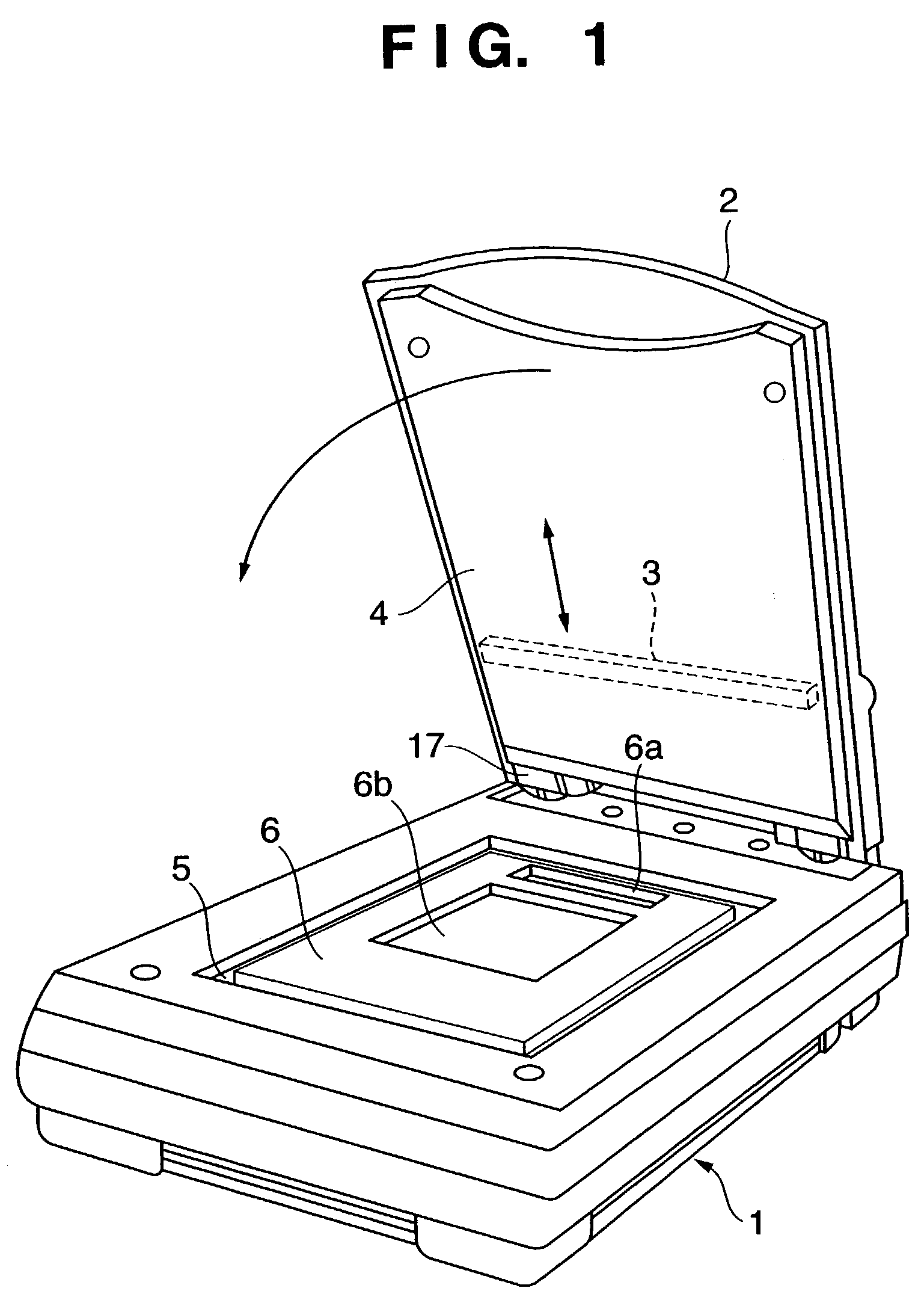
[0060]An image reading apparatus of this embodiment will be described below with reference to FIGS. 1 to 5. FIG. 1 is a schematic perspective view of an image reading apparatus of this embodiment. As shown in FIG. 1, a transparent illumination unit 2 is pivotally attached to an apparatus main body 1 of the image reading apparatus via hinges 17. The transparent illumination unit 2 is used to illuminate a transparent original such as a developed photographic film or the like with light upon reading such transparent original.

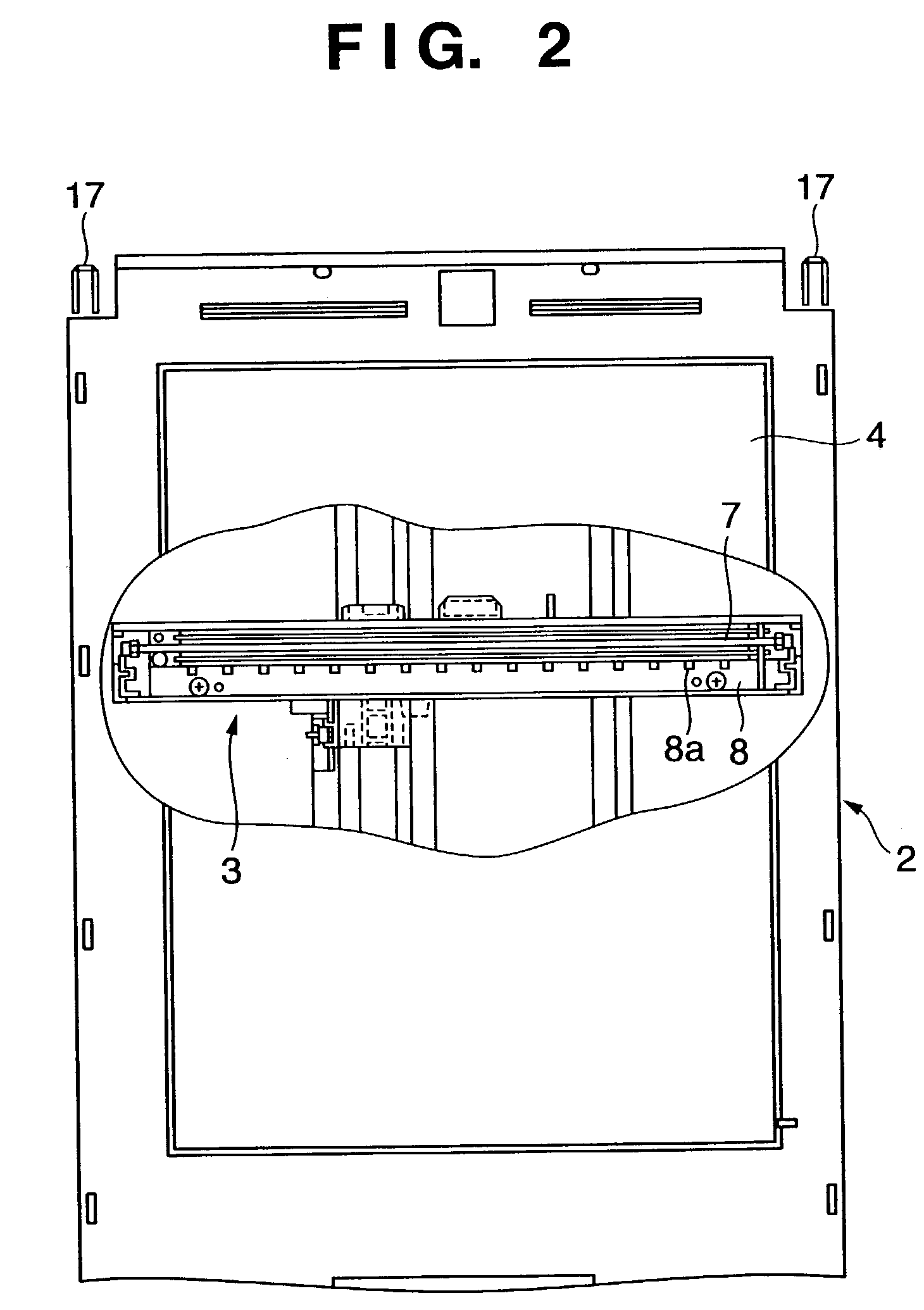
[0061]The transparent illumination unit 2 movably incorporates a light source unit 3 which serves as a transparent original illumination apparatus used to read a transparent original, and its unit lower cover 4 is formed of a translucent member having a light diffusion effect.

[0062]A platen glass 5 on which an original to be read is placed is equipped on the apparatus main body 1 of the image reading apparatus. Upon reading a transparent original, a light-shielding...

second embodiment

[0082]An image reading apparatus according to the second embodiment of the present invention will be described below. In the following description, the same reference numerals denote the same building components as those in the first embodiment described above, and a detailed description thereof will be omitted. FIG. 6 is a schematic bottom view of the transparent illumination unit 2, and FIGS. 7A and 7B are partial sectional views of an image reading apparatus.

[0083]In the light source unit 3 of this embodiment, the transparent original illumination lamp 7 such as a fluorescent lamp, xenon lamp, or the like, which extends in the main scan direction, and a dust / scratch detection LED substrate 16 are arranged parallel to each other as in the first embodiment. Unlike in the first embodiment, an infrared LED 16a which has a luminescence intensity in only an infrared range is arranged at one end of the LED substrate 16, and a light guide member 16b for guiding light emitted by this infr...

third embodiment

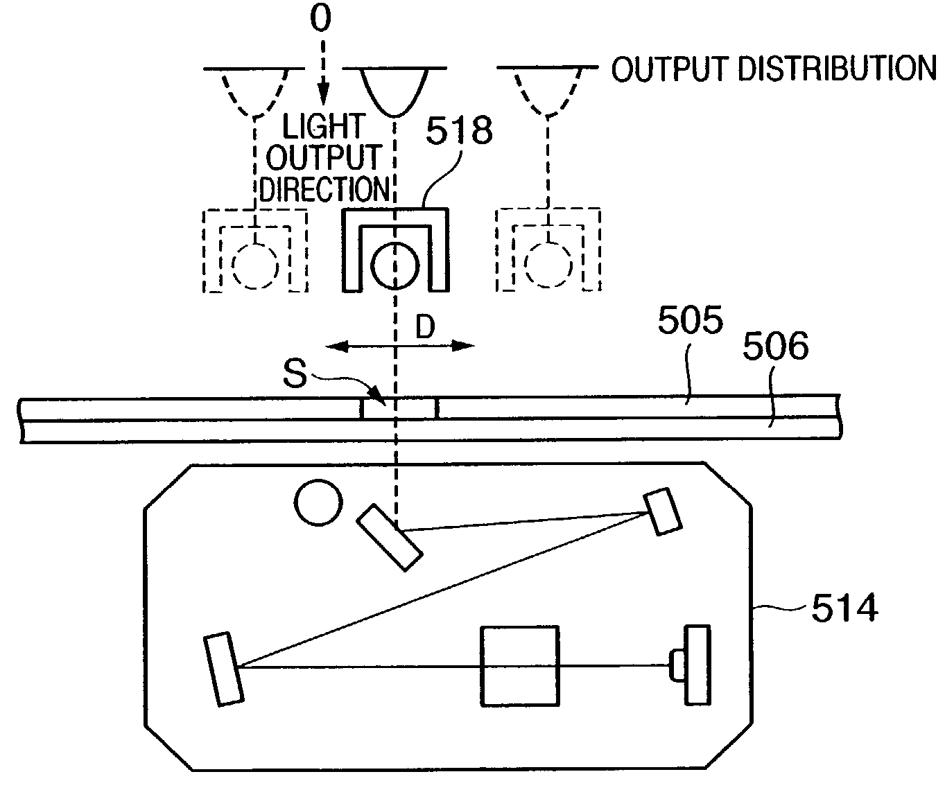
[0092]FIG. 9 is a block diagram showing the arrangement of an image reading apparatus control system that uses a subscanning alignment method of a transparent original illumination unit 328 and optical unit 314 according to the third embodiment of the present invention. In this embodiment, the arrangement of an image reading apparatus is substantially the same as that of the prior art shown in FIG. 22.

[0093]Referring to FIG. 9, the image reading apparatus control system comprises an image reading apparatus 301, transparent original illumination apparatus 302, alignment controller 201, and image processing apparatus 206 as a whole. The image reading apparatus 301 and transparent original illumination apparatus 302 read a predetermined image upon reading a film original. The read image temporarily undergoes an image process in the image processing apparatus via a main scan alignment region determination unit 202 and first subscanning position determination unit 203, and the transparen...


PUM


Abstract

This invention has as its object to obtain a high-quality read image from which dust or scratches have been removed by an image reading apparatus which reads image information on a transparent original by synchronously scanning a light source unit and image reading unit. To this end, upon reading a transparent original, infrared LED chips on a dust / scratch detection LED substrate and a transparent original illumination lamp are turned on to make alignment between the LED substrate and the image reading unit, and dust / scratch detection image information is obtained by synchronously moving the light source unit and image reading unit in the subscanning direction.Subsequently, alignment between the transparent original illumination lamp and image reading unit is made, and image information of the transparent original is obtained by synchronously moving the light source unit and image reading unit in the subscanning direction.

Description

FIELD OF THE INVENTION[0001]The present invention relates to an image reading apparatus for reading image information of an object, a light source unit, a method of controlling an image reading apparatus, a program, and a computer readable storage medium.BACKGROUND OF THE INVENTION[0002]Conventionally, an image reading apparatus 101 which can read a transparent original is comprised of an apparatus main body 103 which includes an image reading device 102, and a transparent original irradiation apparatus 104 which is pivotally arranged on the apparatus main body 103, as shown in FIG. 8. The frame body of the transparent original irradiation apparatus 104 is formed by an upper cover 105 and a translucent lower cover 106 having a light diffusion effect, and it has a light source 107 for scan exposure, and a drive unit (not shown) for moving the light source 107.[0003]When the image reading apparatus with the above arrangement reads image information of a transparent original F, the ori...

Claims


Application Information

Patent Timeline
IPC IPC(8): H04N1/04H04N1/00H04N1/10H04N1/193
CPCH04N1/00002H04N1/00005H04N1/00034H04N1/0005H04N1/00063H04N1/00092H04N2201/041H04N1/1017H04N1/193H04N2201/0406H04N2201/0408
Inventor KOSHIMIZU, MASATOHANABUSA, MITSUGU
Owner CANON KK
Why Eureka
Try Eureka