
Method of displaying 3D image and display apparatus for performing the method

a display apparatus and three-dimensional image technology, applied in the field of three-dimensional image display and display apparatus, can solve the problems of interfering with the use of the display apparatus in displaying 2d images, and achieve the effect of minimizing the deterioration of the resolution of the 3d imag

Active Publication Date: 2013-07-11
SAMSUNG DISPLAY CO LTD
View PDF9 Cites 6 Cited by
  • Summary
  • Abstract
  • Description
  • Claims
  • Application Information

AI Technical Summary

Benefits of technology

The patent is about a way to display 3D images with more viewpoints and better resolution. It uses an active parallax barrier panel that is time-division driven to show multiple images. The panel design and image structure are also carefully thought to minimize any loss of resolution in the 3D image.

Problems solved by technology

As the lenses of the lense-type display and the barrier of the parallax barrier-type displays have traditionally been physically attached to the display apparatus such that they are not removable, the lenses and / or barriers may therefore interfere with the use of the display apparatus in displaying 2D images.

Method used


Image

  • Method of displaying 3D image and display apparatus for performing the method
  • Method of displaying 3D image and display apparatus for performing the method
  • Method of displaying 3D image and display apparatus for performing the method

Examples


Embodiment Construction

[0045]Hereinafter, exemplary embodiments of the present invention will be explained in detail with reference to the accompanying drawings.

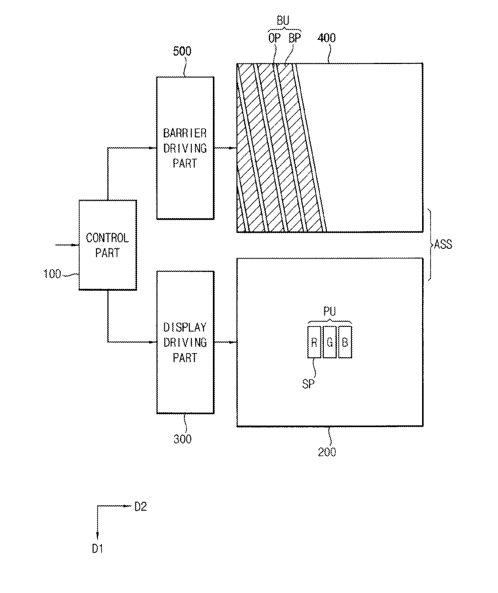
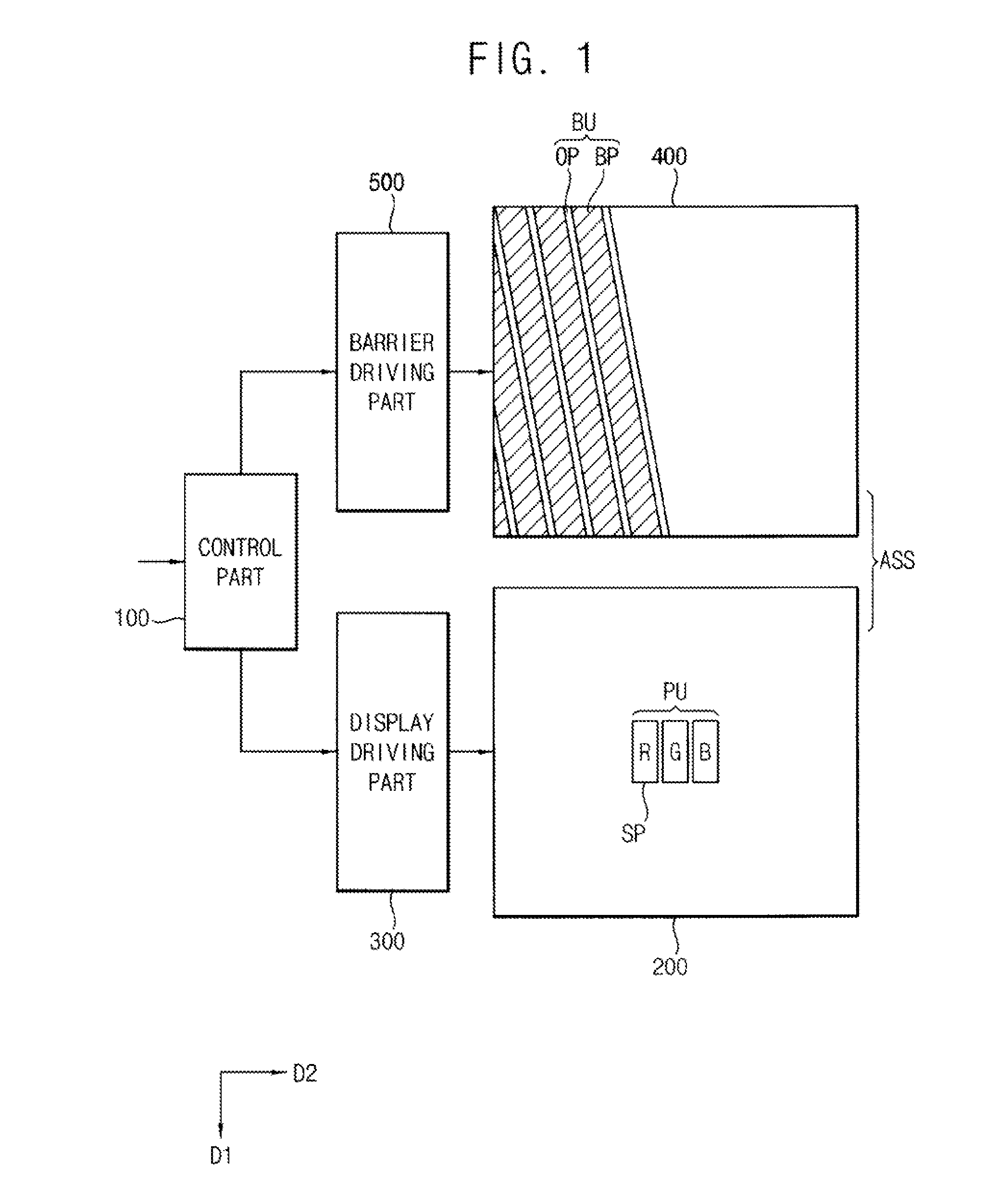
[0046]FIG. 1 is a block diagram schematically illustrating a display apparatus according to an exemplary embodiment of the present invention.

[0047]Referring to FIG. 1, the display apparatus includes a control part 100, a display driving part 300, a barrier driving part 500 and a panel assembly ASS. The panel assembly ASS includes a display panel 200 and an active parallax barrier panel 400.

[0048]The control part 100 receives 2D image data and 3D image data, and controls elements of the display apparatus in a 2D image mode or a 3D image mode based on the received image data.

[0049]When in the 2D image mode, the control part 100 drives the active parallax barrier panel 400 as a transmitting panel in order to provide a 2D image displayed on the display panel 200. When in the 3D image mode, the control part 100 drives the active parallax barrier panel ...


PUM


Abstract

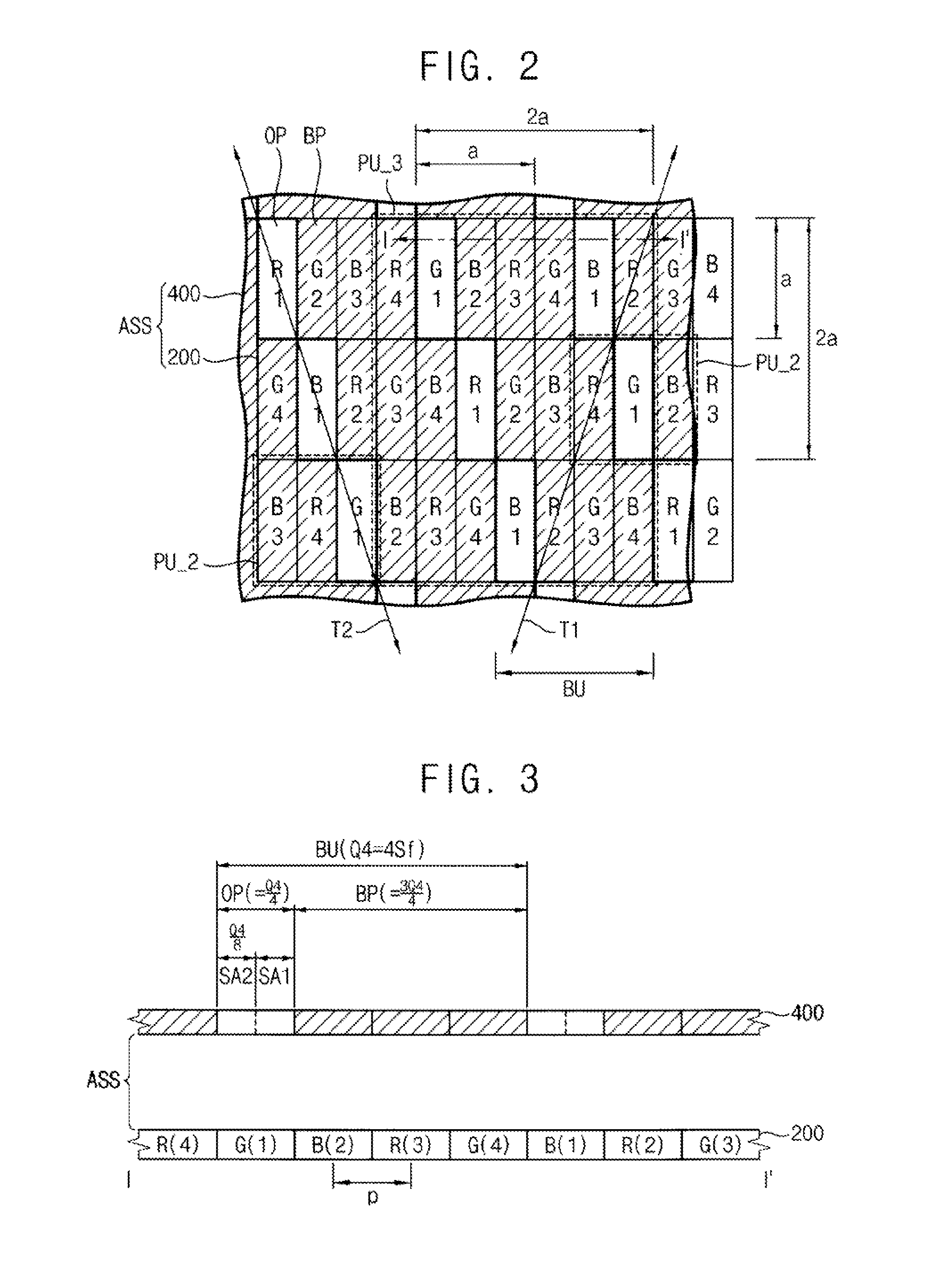
A display apparatus includes a display panel and an active parallax barrier panel. The display panel displays n numbers of viewpoint images on a display panel (‘n’ is natural numbers greater than 2). The active parallax barrier panel includes a plurality of barrier units. Each of the barrier units includes an opening portion and a blocking area divided into m numbers of sub-areas. The active parallax barrier panel selectively opens the m numbers of sub-areas to exit the m numbers of viewpoint images on (n×m) numbers of viewpoint positions (‘m’ is natural numbers greater than 2). Thus, an active parallax barrier panel is time-division driven to display multi-viewpoint images. Moreover, a pixel structure and a barrier structure are alerted, so that deterioration of a resolution of a 3D image may be minimized

Description

CROSS-REFERENCE TO RELATED APPLICATIONS[0001]This application claims priority under 35 U.S.C. §119 to Korean Patent Application No. 10-2012-0001352, filed on Jan. 5, 2012 in the Korean Intellectual Property Office (KIPO), the contents of which are herein incorporated by reference in their entirety.TECHNICAL FIELD[0002]Exemplary embodiments of the present invention relate to a method of displaying a three-dimentional (“3D”) image and a display apparatus for performing the method. More particularly, examplary embodiments of the present invention relate to a method of displaying 3D image which capable of enhancing a display quality of the 3D image and a display apparatus for performing the method.DISCUSSION OF THE RELATED ART[0003]Generally, a display apparatus is capable of displaying two-dimensional images (hereinafter, referred to as 2D images). Recently, according to increasing demands for the display of three-dimensional images (hereinafter, referred to as a 3D images) in fields o...

Claims


Application Information

Patent Timeline
Patent Type & Authority Applications(United States)
IPC IPC(8): G06T15/00
CPCG06T15/00H04N13/00H04N13/045H04N13/0415H04N13/0413H04N13/315H04N13/317H04N13/354
Inventor HAMAGISHI, GORO
Owner SAMSUNG DISPLAY CO LTD
Learn More