Image processing apparatus

a technology of image processing and image, applied in the direction of instruments, visual presentation using printers, electrographic processes, etc., can solve the problems of reducing the processing efficiency of images, increasing the processing time, and increasing the use of memory areas, so as to achieve the effect of small memory capacity

Inactive Publication Date: 2005-06-07
FUJIFILM BUSINESS INNOVATION CORP
View PDF15 Cites 5 Cited by
  • Summary
  • Abstract
  • Description
  • Claims
  • Application Information

AI Technical Summary

Benefits of technology

[0014]In the image processing apparatus according to the present invention, the content of the page description language inputted by the input part is analyzed by the analyzing unit for extracting an area where image deterioration is predicted to occur upon printing, and then, the content of the page description language for describing this extracted area is rewritten by the rewriting part, with the result that the compensation processing can be performed only to the portion where image deterioration occurs. Further, compensation processing is executed by rewriting of the language, to thereby be capable of performing the processing with a smaller memory capacity.
[0015]Moreover, the image processing apparatus according to another aspect of the present invention has an input part for inputting a page description language composed of an image-forming command, an analyzing unit for predicting whether image deterioration will occur or not upon printing by analyzing the content of the page description language inputted by the input part, an image-forming part for forming a raster image according to the content of the page description language inputted by the input part and a compensation processing part for performing, according to the prediction by the analyzing unit, compensation processing on the raster image formed by the image-forming part for reducing image deterioration upon printing.

Problems solved by technology

However, deterioration in image quality upon transferring is pointed out as described in Japanese Unexamined Patent Applications Nos.
However, in the image processing apparatus disclosed in each Application, compensation processing that requires a great number of reference areas is performed to a raster image, to thereby entail an increase in cost due to an increase of the amount of hardware in the case of executing the processing with hardware.
Further, it causes a problem of bringing an increase in processing time and an increase of a used memory area in the case of executing the processing with software.
However, the image processing apparatus disclosed in each Application does not find the area which should be subject to the compensation processing beforehand, so that it is necessary to judge whether the compensation processing should be performed over the entire area in a page or not as well as to execute compensation processing to the area that is judged to be subject to compensation processing, thereby entailing an increase in processing time.

Method used


Image

  • Image processing apparatus
  • Image processing apparatus
  • Image processing apparatus

Examples


first embodiment

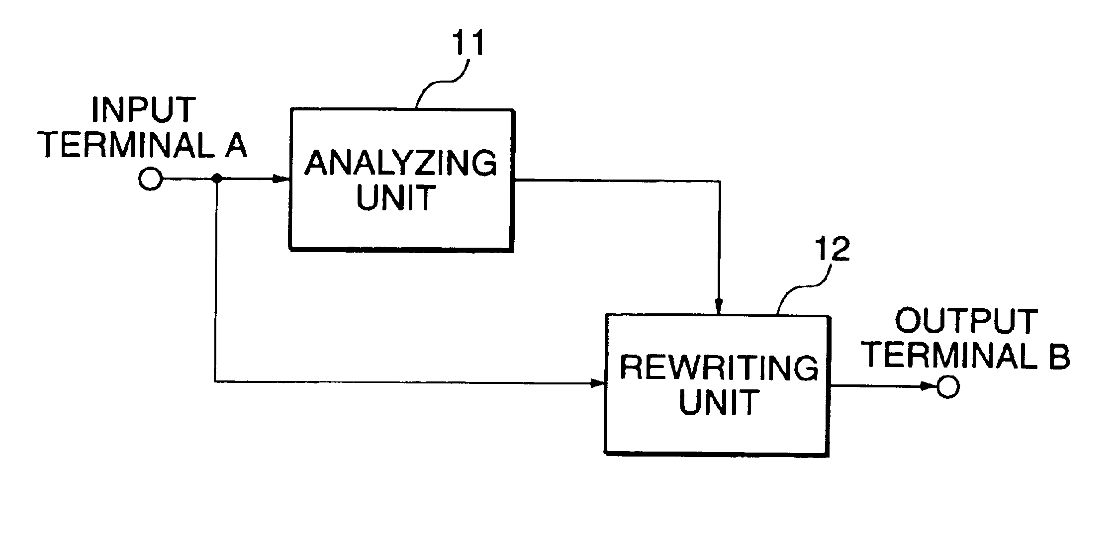
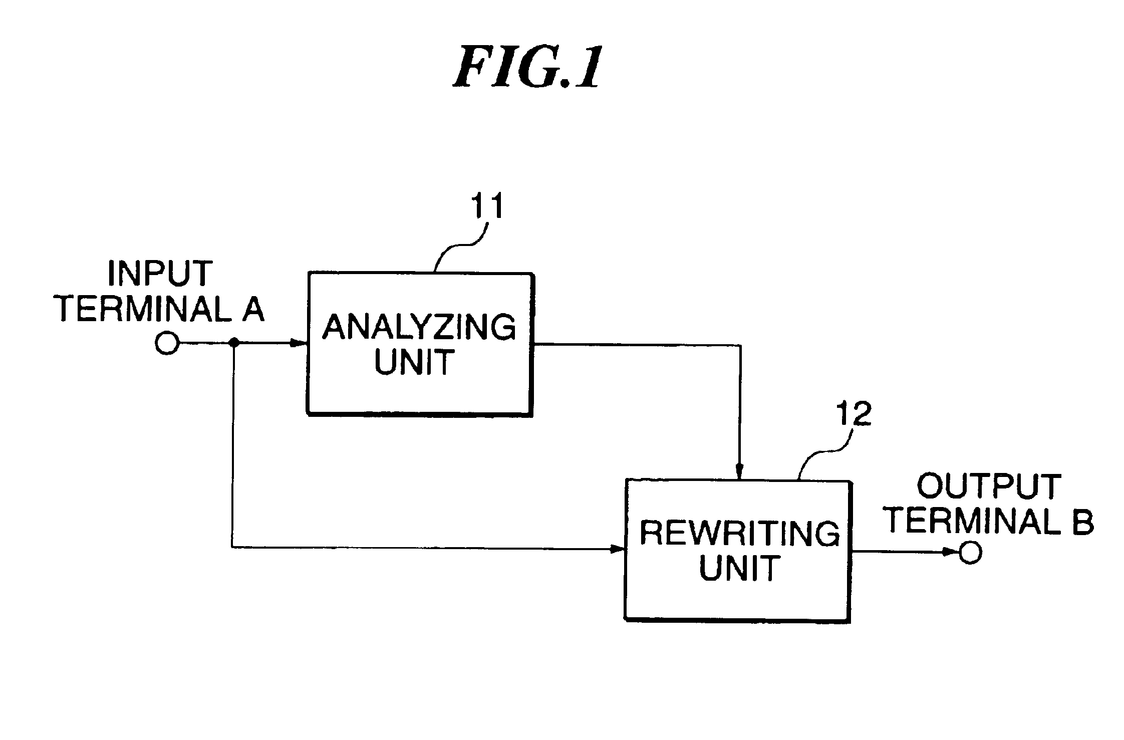
[0036]FIG. 1 is a configuration view for explaining the first embodiment. Specifically, this image processing apparatus is provided mainly with an input terminal A, an analyzing unit 11 and a rewriting unit 12.

[0037]The input terminal A inputs a page description language (referred to simply as PDL hereinafter) that is composed of an image-forming command and outputted from an external application software or the like. The analyzing unit 11 detects a portion where image deterioration upon printing (referred to simply as image deterioration hereinafter) is predicted from the PDL inputted to the input terminal A, and then, outputs the detected result to the rewriting unit 12.

[0038]The rewriting unit 12 rewrites a content of the PDL inputted to the input terminal A according to the detected result outputted from the analyzing unit 11, and then, outputs to the outside via an output terminal B. The PDL outputted from the output terminal B is converted into a raster image that can be print...

second embodiment

[0062]FIG. 6 is a configuration view for explaining the second embodiment. Specifically, this image processing apparatus is mainly provided with the input terminal A, analyzing unit 11, rasterizing unit 13 and compensation processing unit 14.

[0063]The input terminal A inputs a PDL composed of an image-forming command outputted from the external application software or the like. The analyzing unit 11 detects a portion where image deterioration is predicted to occur from the PDL inputted to the input terminal A and outputs the detected result to the compensation processing unit 14.

[0064]The rasterizing unit 13 converts the PDL inputted to the input terminal A into a raster image according to its content and outputs the resultant to the compensation processing unit 14. The compensation processing unit 14 performs compensation processing on the raster image outputted from the rasterizing unit 13 according to the detected result outputted from the analyzing unit 11 and then outputs the r...

third embodiment

[0075]FIG. 7 is a configuration view for explaining an image processing apparatus in the third embodiment. Specifically, this image processing apparatus is mainly provided with the input terminal A, analyzing unit 11 and rasterizing unit 13. The analyzing unit 11 detects the portion where image deterioration is predicted to occur from the PDL inputted to the input terminal A and then outputs the detected result to the outside from the output terminal B. Further, the rasterizing unit 13 converts the PDL inputted to the input terminal A into a raster image according to its content and then outputs the resultant to the outside from an output terminal C.

[0076]Although, in this embodiment, the operation for detecting by the analyzing unit 11 the portion where image deterioration is predicted to occur and the rasterizing processing by the rasterizing unit 13 are the same as those in the second embodiment, it is different from the second embodiment in that the result of the portion where i...


PUM


Abstract

An image processing apparatus of the present invention is provided with an input terminal for inputting a page description language composed of an image-forming command, an analyzing unit for detecting whether image deterioration will occur or not upon printing by analyzing a content of the page description language inputted by the input terminal and a rewriting part for rewriting the content of the inputted page description language according to the result of the detection by the analyzing unit.

Description

BACKGROUND OF THE INVENTION[0001]1. Field of the Invention[0002]The present invention relates to an image processing apparatus, and more particularly to an image processing apparatus that compensates deterioration in an image quality upon printing.[0003]2. Description of the Prior Arts[0004]In recent years, printers have spread to offices in general and homes. The improvement of their performance has been remarkable. Printers are classified into several types according to its printing method, among which an electrophotographic printer has a feature of high image quality and high productivity.[0005]In this electrophotographic printer, toner is adhered onto an electrophotographic latent image obtained on a photosensitive member according to ON or OFF of a light emitting device such as a laser diode for developing the latent image, and the developed image is transferred to be fixed on an output medium such as a paper sheet or an OHP sheet, whereby a desired printed-out image can be obt...

Claims


Application Information

Patent Timeline
Patent Type & Authority Patents(United States)
IPC IPC(8): B41J2/52G03G15/00G06F15/00B41J2/485G06K15/02
CPCG06K15/005G06K15/1822G06K15/02
Inventor KAWANO, HIROYUKISEKINE, HIROSHIMORI, MIKIHIRO
Owner FUJIFILM BUSINESS INNOVATION CORP
Why Eureka
Try Eureka