Conveying device with configuration change

a conveying device and configuration technology, applied in the field of conveying devices, can solve the problems of avoiding the necessity of connecting a central computer for configuration purposes, reducing the cost of operation, and limiting the use of conveying devices, so as to reliably prevent the inadvertent entry of a configuration change command

Active Publication Date: 2018-03-29
INTERROLL HLDG
View PDF0 Cites 2 Cited by
  • Summary
  • Abstract
  • Description
  • Claims
  • Application Information

AI Technical Summary

Benefits of technology

[0019]It is also preferred that the first control configuration includes a first bus protocol for configuring the data communication via the bus communication, and the second or other control configuration different from the first includes a second bus protocol different from the first for configuring the data communication via the bus communication. According to this embodiment, it is possible to select from two different bus protocols by changing the control configuration. This enables the control unit or conveying device according to the invention to operate selectively with at least two, preferably with several different bus protocols and to communicate via bus communication in accordance with a bus protocol selected therefrom. It should be understood, as a basic principle, that by means of the bus protocol, it is possible to adapt transmission between the control unit or within the conveying device to different transmission media (e.g., radio, waveguides, Ethernet, CAN, RS 485, RS 232) and to different communication protocols (e.g., TCP / IP, CAN, Ethernet / IP, Profinet, Profibus, Modbus).
[0020]It is still further preferred that the first control configuration includes a first control method which configures the microprocessor to receive control commands via bus communication and to route said control commands to the conveyor drive in a central control mode, and the second or other control configuration different from the first includes a second control method different from the first, which configures the microprocessor to receive a busy signal and / or a conveying signal from a control unit of a neighbouring conveyor segment and to logically generate a control command in the microprocessor from said busy signal and / or conveying signal and to send said control command to the conveyor drive in a decentral control mode. This preferred embodiment provides the conveying device according to the invention, or the control unit used therein, with a multifunction capability. By adapting the control configurations accordingly to different types of control, for example, decentralised control or centralised control, the control units can be adapted and configured to route signals or to perform logic signal processing decentrally. Compared to the solutions known hitherto, in which control programs are stored in read-only memories inside the control unit and therefore cannot be changed, it is possible according to the invention for a large number of different control configurations, for example, more than 100, to be stored in the second electronic memory and for each of these control configurations to be loaded selectively into the first electronic memory in order to induce a respective operating mode. The control configurations preferably include, in the form of status tables, the description of the conveying process, in that the control processes are described as state machines in those status tables. This means that storing the control processes requires a very compact amount of memory compared to machine commands that are otherwise necessary and, thus, that a microcontroller with relatively little memory capacity can be installed in the first electronic memory in the control unit.
[0021]According to another preferred embodiment, the first control configuration includes a first control method which configures the microprocessor to control a first conveying mode, and the second or other control configuration different from the first includes a second control method different from the first, which configures the microprocessor to control a second conveying mode different from the first, wherein the first and / or second conveying mode is preferably selected from a single take-off mode in which the microprocessor activates the conveyor drive of a conveyor segment when it receives a signal indicating that a neighbouring downstream conveyor segment is not busy, a block take-off mode in which the microprocessor activates the conveyor drive of a conveyor segment when it receives a signal indicating that the conveyor drive or a neighbouring downstream conveyor segment is activated, a transfer mode in which the microprocessor is configured to control a conveyor drive and a transfer drive which horizontally inserts or ejects the conveyed object from the conveyor segment, a lift mode in which the microprocessor is configured to control a conveyor drive and a lift drive which vertically inserts or ejects the conveyed object from the conveyor segment, and a sort mode in which the microprocessor is configured to receive a sorting signal and to control a conveyor drive and a sorting drive which sorts the conveyed object according to the received sorting signal into at least two, preferably into a plurality of, different exits from the conveyor segment.
[0022]According to this embodiment, it is possible to select from two different conveying modes that are stored in the second electronic memory. This allows the conveyor segments in a conveyor line to be rapidly configured in one of several possible conveying modes. They can also be configured in such a way that individual conveyor segments are configured with differing conveying modes. A conveying mode should be understood here as a mode of operation which defines a process of conveying the objects, on the basis of a predefined bus protocol and a predefined, decentralised control configuration. Such a conveying process can be implemented, in particular, by zero pressure accumulation (ZPA) modes of operation, in which the individual conveyor segments are controlled in such a way that the objects are conveyed without coming into contact with one another. This can take the form of single take-off, for example, in which an object is conveyed to the next downstream conveyor segment exactly when the next conveyor segment is free, which is typically detected and signalled by a respective sensor in the next conveyor segment. Block take-off may also be configured as a ZPA operating mode, in which an object is conveyed into the next downstream conveyor segment at exactly the moment in which the object on the next conveyor segment is passed on, which is typically detected and signalled by a respective activation signal from the conveyor drive of the next conveyor segment. Other conveying modes relate to specific conveyor segments with additional functions, such as switch points (with merge or divert functions), elevator systems, a sorting function using a code reader, and a system for distribution to two or more alternative conveyor segment exits, and the like. In these cases, the control unit performs the additional control functions for such conveyor segments via additional signal inputs and / or outputs.
[0023]According to another preferred embodiment, the conveying device includes a manual user interface connected to the microprocessor, and the microprocessor is adapted to process a signal received as a configuration change command via the user interface. It should be understood, as a basic principle, that all the configuration processes within the controller according to the invention can be carried out by connecting a separate configuration computer, or by a software control system on a central control computer which is connected to the bus communication. However, the necessity of connecting a central computer for configuration purposes can be avoided, according to this embodiment, by equipping the control units with a user interface that allows a configuration change command to be entered. This manual user interface can be provided in the form of a mechanical pushbutton, actuator button, touchscreen, or the like, and, in particular, as a binary switch having two states, or a multi-switch having several states.
[0024]According to a particularly preferred embodiment in this regard, the manual user interface is a switch which can be triggered with a magnetic signal, in particular a Reed contact or a Hall effect sensor. Such a switch, which can be triggered with a magnetic signal, can reliably prevent a configuration change command being entered inadvertently, for example, by inadvertently touching a switch or pushbutton. With such a magnetically operated switch, it is possible, in particular, to ensure that a configuration is changed only by authorised persons, for example, in that the switch can only be triggered by a magnetic field strength which is within a specific range defined by a lower and an upper limit, and by such a magnet for triggering the switch being issued only to persons who have the respective authorisation.

Problems solved by technology

Due to the very large number of control units that must be installed in larger conveyor systems, these control units account for a significant proportion of the total costs of the conveyor system and are subject as a consequence to considerable pressure to minimise costs.
One disadvantage of the enormous variety that conveyor systems fundamentally show, however, is that system components from different conveyor systems are interchangeable to only a minimal extent, if at all.
It is generally impossible for the user of such conveying devices to combine components of conveyor systems made by different manufacturers, or it is necessary for components to be individually adapted.
There are often incompatibilities even between components of different generations of conveyor systems made by one and the same manufacturer.
Such extensive storage facilities and the concomitant need to provide production capacities for a large number of different conveyor systems, causes additional costs for the manufacturers of such conveying devices.
This stands in contradiction to the actual aim of providing such conveying devices cost-efficiently.

Method used


Image

  • Conveying device with configuration change
  • Conveying device with configuration change
  • Conveying device with configuration change

Examples


Embodiment Construction

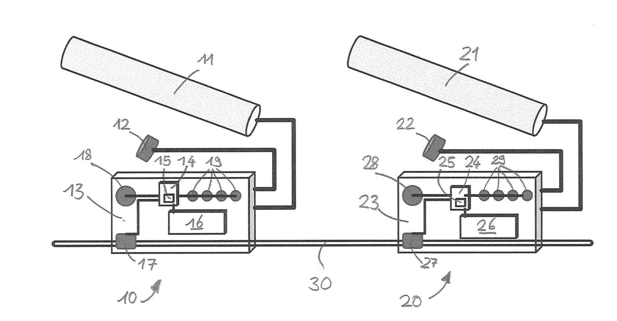
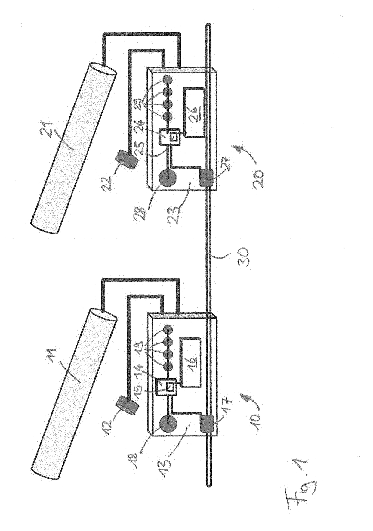
[0039]As referenced in the Figures, the same reference numerals may be used herein to refer to the same parameters and components or their similar modifications and alternatives. For purposes of description herein, the terms “upper,”“lower,”“right,”“left,”“rear,”“front,”“vertical,”“horizontal,” and derivatives thereof shall relate to the present disclosure as oriented in FIG. 1. However, it is to be understood that the present disclosure may assume various alternative orientations and step sequences, except where expressly specified to the contrary. It is also to be understood that the specific devices and processes illustrated in the attached drawings, and described in the following specification, are simply exemplary embodiments of the inventive concepts defined in the appended claims. Hence, specific dimensions and other physical characteristics relating to the embodiments disclosed herein are not to be considered as limiting, unless the claims expressly state otherwise. The draw...


PUM


Abstract

The invention relates to a conveying device for conveying objects comprising a plurality of conveyor segments, each conveyor segment having a control unit for controlling the conveyor drive, and a bus communication, wherein each control unit is connected to the bus communication. Each control unit has a microprocessor for processing control signals, a first electronic memory connected to the microprocessor, in which a first control configuration is stored, and a second electronic memory in which a second control configuration is stored. The microprocessor is adapted to control the conveyor drive in a first operating mode with the control configuration stored in the first memory, to load the second control configuration from the second memory into the first memory when a configuration change command is received, and to control the conveyor drive in a first operating mode with the control configuration stored in the first memory.

Description

CROSS-REFERENCE TO FOREIGN PRIORITY APPLICATION[0001]The present application claims the benefit under 35 U.S.C. § 119(b) of PCT / EP2016 / 058756, filed Apr. 20, 2016, which claims priority to German Application No. 102015106024.8, filed Apr. 20, 2015, entitled “Conveying Device with Configuration Change.”FIELD OF THE INVENTION[0002]The invention relates to a conveying device for conveying objects such as containers or parcels, comprising a plurality of conveyor segments, each conveyor segment having a control unit for controlling the conveyor drive and a bus communication, wherein each control unit is connected to the bus communication to send and / or receive control signals via bus communication. Another aspect of the invention concerns a method for controlling a conveying device for conveying objects such as containers or parcels, said conveying device comprising a plurality of conveyor segments, each conveyor segment having a conveyor drive, and a control unit having a microprocessor...

Claims


Application Information

Patent Timeline
Patent Type & Authority Applications(United States)
IPC IPC(8): B65G43/00G05B19/042
CPCB65G43/00G05B19/0426G05B2219/25092G05B2219/25204G05B2219/2621G05B19/056G05B19/41845G05B19/4186G05B2219/23193Y02P90/02G05B19/4189B65G43/10
Inventor HENZE, HERBERT
Owner INTERROLL HLDG
Why Eureka
Try Eureka