Projection optical system and projector including the same

a projection optical system and projector technology, applied in the direction of instruments, printers, cameras, etc., can solve the problems of deteriorating an image, increasing and complicating the adjustment of the entire projection optical system including the converter, so as to prevent an increase in the size of the projector or image deterioration.

Active Publication Date: 2014-08-12
SEIKO EPSON CORP
View PDF9 Cites 6 Cited by
  • Summary
  • Abstract
  • Description
  • Claims
  • Application Information

AI Technical Summary

Benefits of technology

[0009]An advantage of some aspects of the invention is that it provides a projection optical system and a projector equipped with the same capable of preventing an increase in size of a projector or image deterioration.

Problems solved by technology

This kind of converter is provided as an external optical unit which is independent of a projector body, causing an increase in size of the projector, complicating adjustment of the entire projection optical system including the converter, or significantly deteriorating an image.
In general, it is difficult to manufacture a rotationally asymmetrical optical component, and from the viewpoint of precision, reduction in size is indispensably required.
Meanwhile, astigmatism in the horizontal direction is not easily corrected.

Method used


Image

  • Projection optical system and projector including the same
  • Projection optical system and projector including the same
  • Projection optical system and projector including the same

Examples


first embodiment

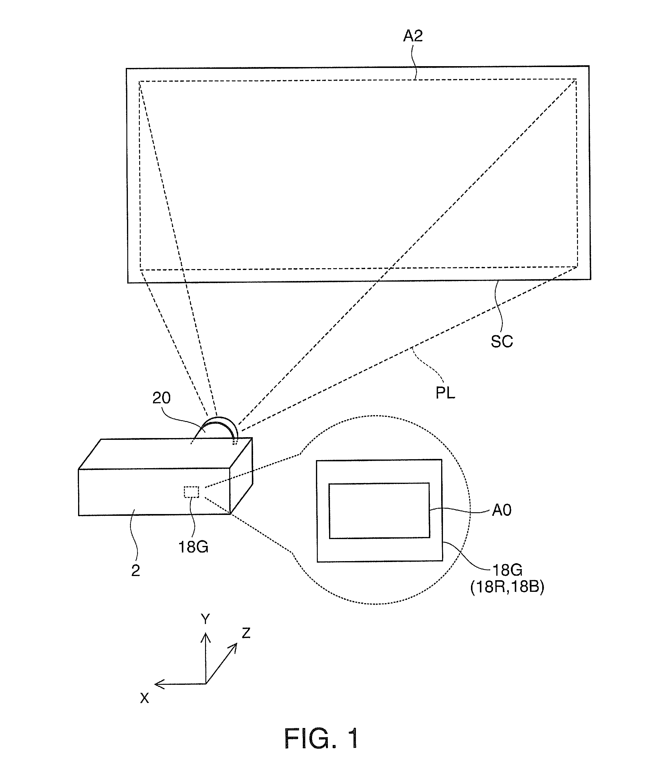
[0094]As shown in FIG. 1, a projector 2 according to a first embodiment of the invention forms image light PL in accordance with an image signal, and projects the image light PL toward a projection surface, such as a screen SC. When projecting an image of liquid crystal panel 18G (18R, 18B) serving as an optical modulator in the projector 2 onto a screen (projection surface) SC on an enlarged scale, a projection optical system 20 of the projector 2 can differ the aspect ratio AR2 of the image projected onto the screen SC from the aspect ratio AR0 of the image of the liquid crystal panel 18G (18R, 18B). That is, the aspect ratio AR0 of a display area A0 of the liquid crystal panel 18G and the aspect ratio AR2 of a display area A2 of the screen SC may be identical or may be different. Specifically, the aspect ratio AR0 of the display area A0 of the liquid crystal panel 18G is, for example, 1.78:1, and the aspect ratio AR2 of the display area A2 of the screen SC is, for example, 1.78:1...

example 1

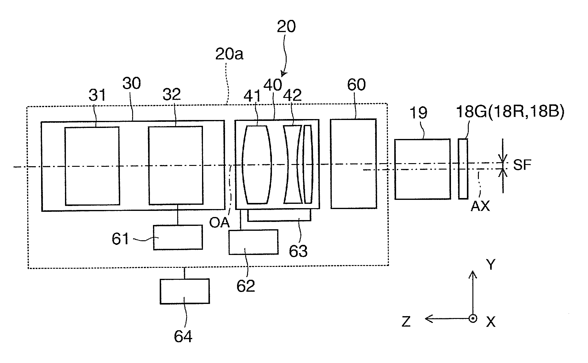
[0124]FIG. 8 is a diagram illustrating Example 1 of the projection optical system 20 of the first embodiment. In this case, the projection optical system 20 is in the first operation state where the second group 40 is disposed on the optical path to compress the aspect ratio in the vertical Y direction. In this case, the projection optical system 20 has lenses L1 to L24. Of these, the lenses L1 to L17 form a first group 30, the lenses L18 to L22 form a second group 40, and the lenses L23 and L24 form a third group 60. The lenses L1 to L17 in the first group 30 are spherical lenses which are rotationally symmetrical around the optical axis OA. In the second group 40, a lens in which the cemented lenses L18 and L19 and the lens L20 are combined is a cylindrical lens which has positive power in the vertical Y direction, and has no power in the horizontal X direction. The cemented lenses L21 and L22 are cylindrical lenses which have negative power in the vertical Y direction, and have n...

second embodiment

[0132]Hereinafter, a projection optical system or the like according to a second embodiment will be described. This embodiment is a modification of the projection optical system or the like of the first embodiment, and portions or matters which will not be particularly described are the same as those in the first embodiment.

[0133]FIGS. 12A and 12B are diagrams illustrating a longitudinal section of a projection optical system 20 according to the second embodiment. In this embodiment, the second group 40 of the projection optical system 20 is advanced and retreated on the optical path, and when the second group 40 for aspect ratio conversion is retreated from the optical path, an alternative optical element 240 which is a flat plate of no power is inserted on the optical path. The alternative optical element 240 has, for example, one plate-shaped member 241, but may have two or more plate-shaped members. The plate-shaped member 241 has no refractive power but has high transparency, a...


PUM


Abstract

A projection optical system which, when projecting an image of an optical modulator onto a projection surface on an enlarged scale, differs the aspect ratio of the image of the optical modulator and the aspect ratio of the image projected onto the projection surface, and includes, in order from the projection surface, a first group which is an enlargement optical system; a second group includes an adjustment optical component with a surface rotationally asymmetrical to an optical axis, when defining at least one direction of the vertical direction and the horizontal direction of the optical modulator as an adjustment direction in which conversion adjustment using compression or extension is performed, the adjustment optical component having at least one optical system which differs in power between the adjustment direction and another direction; and a third group which has a correction optical component with a surface rotationally symmetrical to the optical axis.

Description

BACKGROUND[0001]1. Technical Field[0002]The present invention relates to a projection optical system and a projector including the same capable of switching the aspect ratio of a projected image, and in particular, to a projection optical system and a projector in which an optical unit for aspect ratio conversion is detachably mounted.[0003]2. Related Art[0004]As a converter for aspect ratio conversion which is used in a projection optical system of a projector, there is a front-disposed converter which is retreatably disposed at a front position of an existing projection optical system, that is, in front of the image side.[0005]This kind of converter is provided as an external optical unit which is independent of a projector body, causing an increase in size of the projector, complicating adjustment of the entire projection optical system including the converter, or significantly deteriorating an image.[0006]As a converter for aspect ratio conversion which is used in an image-takin...

Claims


Application Information

Patent Timeline
Patent Type & Authority Patents(United States)
IPC IPC(8): G03B21/00G02B3/02G02B13/08G02B13/12G02B13/16G02B13/18G03B21/14G03B33/12
CPCG02B13/12G02B13/16G03B21/142G03B33/12
Inventor MORIKUNI, EIJIOTANI, MAKOTO
Owner SEIKO EPSON CORP
Why Eureka
Try Eureka