Frame for image forming apparatus and manufacturing method thereof

a technology of image forming apparatus and manufacturing method, which is applied in the direction of electrographic process, manufacturing tools, instruments, etc., can solve the problems of weak rigidity with respect to directions of being and torsion, inability to maintain distance accuracy between respective parts, and image quality, so as to suppress an increase in cost and improve rigidity of the frame

Active Publication Date: 2015-08-06
CANON KK
View PDF5 Cites 11 Cited by
  • Summary
  • Abstract
  • Description
  • Claims
  • Application Information

AI Technical Summary

Benefits of technology

[0014]A principal object of the p resent invention is to maintain and improve rigidity of a frame for an image forming apparatus while suppressing an increase in cost and upsizing of the image forming apparatus.

Problems solved by technology

In the metal plate-combined frame, the parts constituting the frame are flat plates, and therefore there is a problem such that rigidity with respect to directions of being and torsion is weak.
When the rigidity of the frame is weak, an entirety of the image forming apparatus contorts and thus positional relationships among various parts held by the frame are disordered, so that distance accuracy between respective parts cannot be maintained.
Particularly, between the optical scanning unit and a photosensitive member, in the case where the distance accuracy cannot be ensured, there is a liability that major defect, in terms of an image quality, such as image distortion or color misregistration generates.
In order to compensate for insufficient strength of the frame as described above, when an increase in thickness of the metal plate, addition of a reinforcing member and the like are made, increases in number of parts, weight, cost and the like generate, thus being contrary to downsizing and low price.
However, in the metal plate-combined frame of the conventional image forming apparatus shown in FIGS. 9-12, the following problem occurred.
In a state in which the loosening torque is low, screw deviation is caused due to impact (shock) or the like during transportation of the image forming apparatus, so that the entirety of the image forming apparatus is distorted in some cases.
As a result, there is a liability that the supporting stay itself increases in cost.
Further, there is a need to provide a fastening position of the fastening means 107 in a position spaced from a body portion of the supporting stay to some extent, and therefore there is a liability that the image forming apparatus is upsized correspondingly.

Method used


Image

  • Frame for image forming apparatus and manufacturing method thereof
  • Frame for image forming apparatus and manufacturing method thereof
  • Frame for image forming apparatus and manufacturing method thereof

Examples


Embodiment Construction

[0032]Hereinbelow, embodiments of the present invention will be specifically described with reference to the drawings.

[0033]However, dimensions, materials and shapes of constituent elements and their relative arrangements and the like described in the following embodiments should be changed appropriately depending on structures and various conditions of apparatuses (devices) to which the present invention is applied, and the scope of the present invention is not intended to be limited to the following embodiments.

(Image forming apparatus)

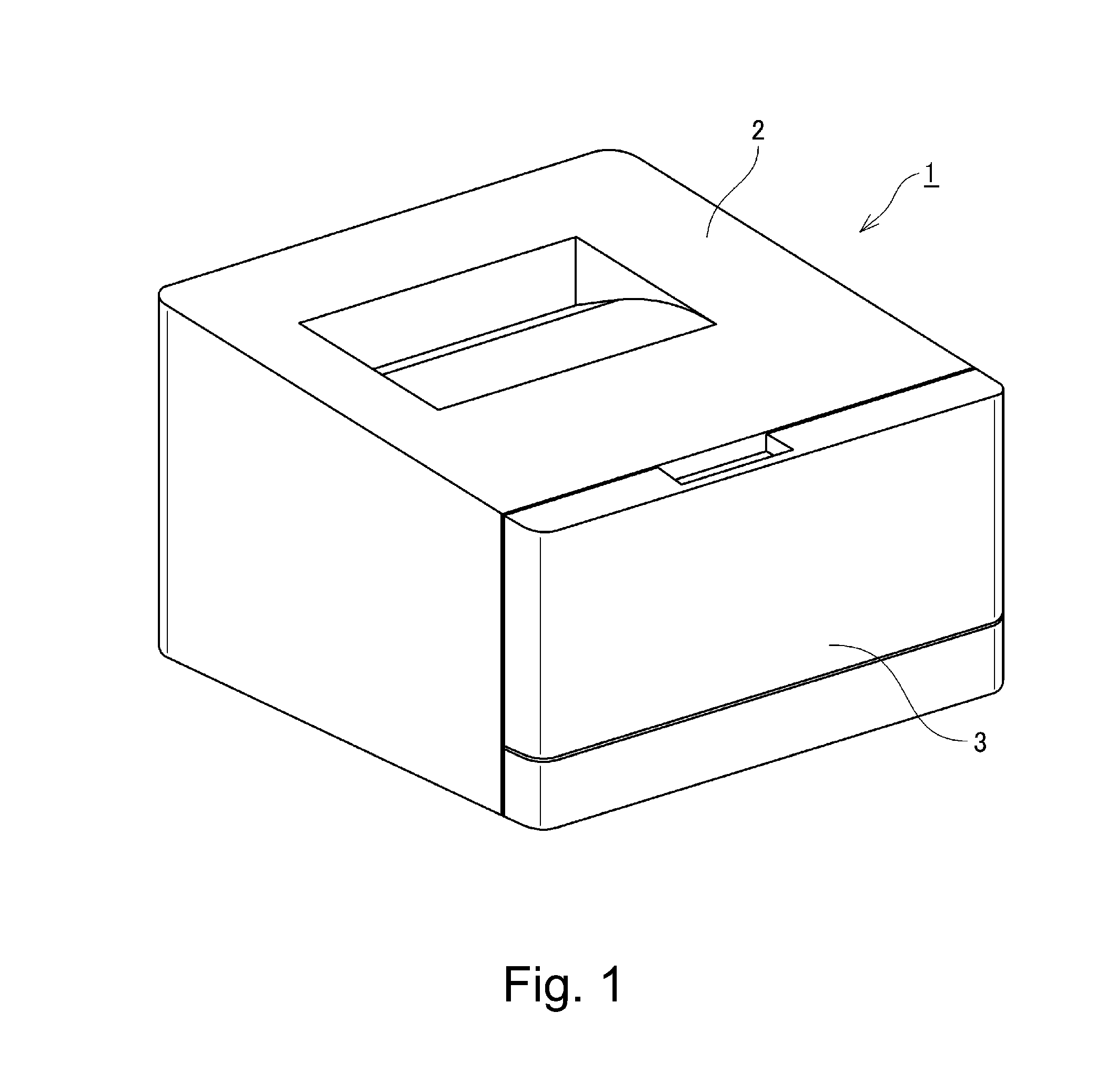
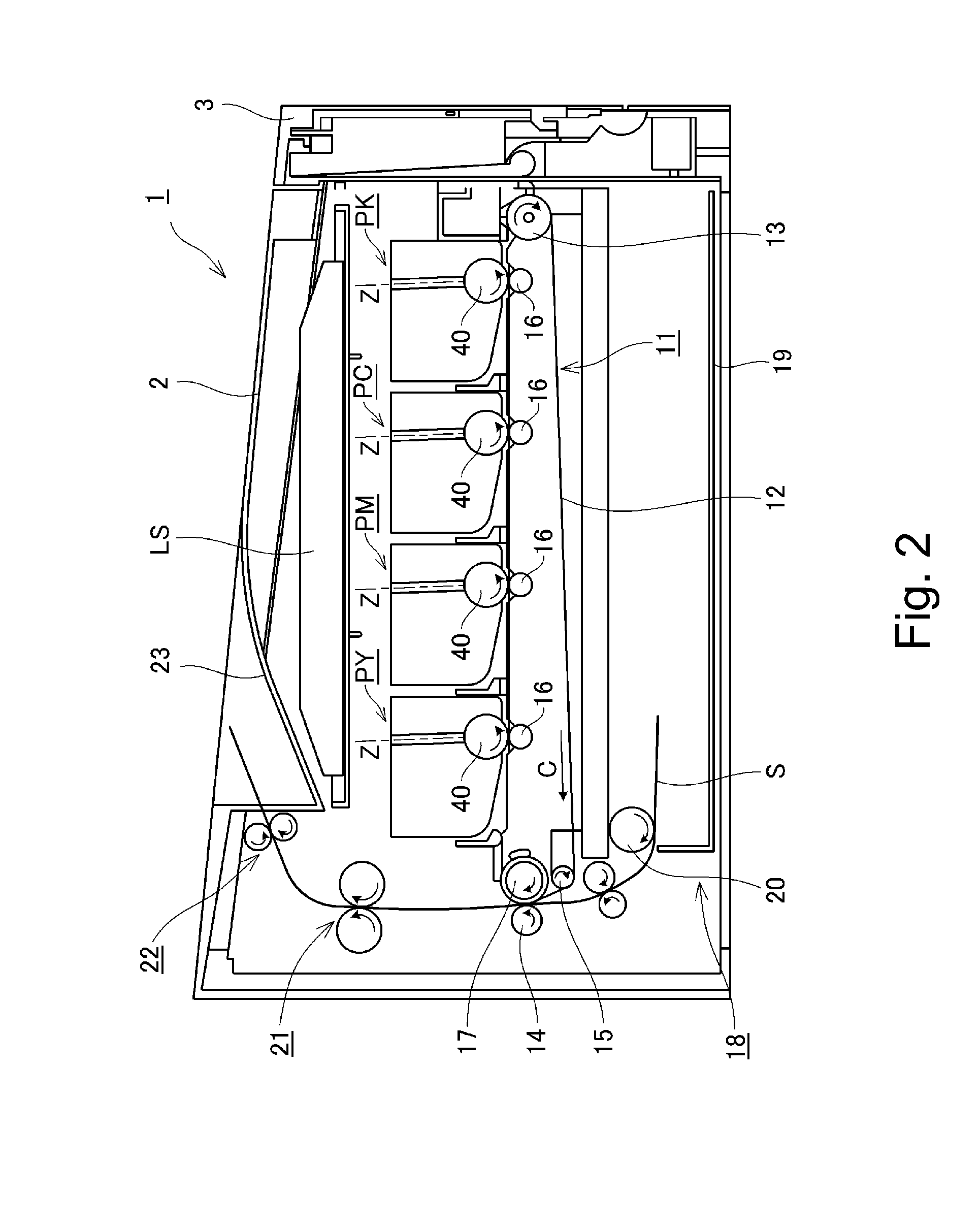
[0034]First, with reference to FIGS. 1 and 2, a general structure of an image forming apparatus in an embodiment of the present invention will be described. FIG. 1 is a perspective view of an outer appearance of the image forming apparatus in this embodiment. FIG. 2 is a schematic sectional view showing a structure of the image forming apparatus in this embodiment.

[0035]An electrophotographic image forming apparatus 1 in this embodiment is a four-co...


PUM

PropertyMeasurementUnit
closest distanceaaaaaaaaaa
thicknessaaaaaaaaaa
thicknessaaaaaaaaaa

Abstract

A frame for an image forming apparatus, includes: first and second plate members; a bent portion provided as a part of the first plate member and bent along the second plate member; a portion-to-be-fixed provided as a part of the bent portion; a positioning portion, provided on the first plate member, for positioning the second plate member relative to the first plate member by being abutted vertically against the second plate member, wherein a free end projects toward the second plate member more than the portion-to-be-fixed; and a fixing portion, provided as a part of the second plate member, to which the portion-to-be-fixed is fixed. The second plate member is deformed to contact and deform the fixing portion to the portion-to-be-fixed while the second plate member is in contact to the positioning portion, so that the first plate member and the second member are fixed to each other.

Description

FIELD OF THE INVENTION AND RELATED ART[0001]The present invention relates to a frame for an image forming apparatus and a manufacturing method of the frame.[0002]In recent years, with respect to the image forming apparatus, in order to meet demands for downsizing and price reduction, designed cost reduction efforts have been made repeatedly. In a conventional image forming apparatus, as a frame (casing) for mounting parts of an entirety of a main assembly, a metal plate-combined frame which is a combination of simple metal plates has been employed. The metal plate-combined frame has advantages, compared with a large-sized integral mold frame or the like, such that a material cost is stable, accuracy is easily ensured, a mold investment is less, parts are flat plates and therefore a distribution cost is low.[0003]The metal plate-combined frame is constituted by left and right side plates, flat metal plates such as an optical stay for mounting an optical scanning unit using a laser or...

Claims


Application Information

Patent Timeline
Patent Type & Authority Applications(United States)
IPC IPC(8): G03G15/00B23P11/00
CPCB23P11/00G03G21/1619G03G2215/0132Y10T29/49908
Inventor SUZUKI, TETSUJIYAMASHITA, MASATOSHI
Owner CANON KK
Why Eureka
Try Eureka