Image forming apparatus

a technology of image forming apparatus and forming chamber, which is applied in the direction of electrographic process apparatus, thin material handling, instruments, etc., can solve the problems of long time required, print defects are generated due to the compact design of it is difficult to achieve a compact design for the image forming apparatus

Active Publication Date: 2006-09-28
SHARP KK
View PDF2 Cites 6 Cited by
  • Summary
  • Abstract
  • Description
  • Claims
  • Application Information

AI Technical Summary

Problems solved by technology

That is, because a large middle tray is necessary, it becomes difficult to achieve a compact design for the image forming apparatus.
Also, with this first method, when multiple sheets of duplex printing are requested, because back side printing is begun after front side printing of all of these multiple sheets is completed, a long time is required until the user obtains recording paper that has been printed on both sides (until the print status of the first page of printed material can be confirmed).
This sort of difference in transfer voltage exerts a large influence on the transfer properties for front side printing and back side printing, and invites defects wherein the print quality of the front side and the back side is not the same.
On the other hand, when duplex printing is performed for multiple sheets, when printing the front side of the second and subsequent sheets, print defects are generated due to “photographic fog”, described below.
However, when performing the transfer process for the back side of the first sheet of paper, because the paper has been through the fixing process when printing the front side, as described above, the resistance value of the paper has increased, and because of that increase in the resistance value the transfer current cannot easily flow.
This method attempts to maintain a constant current by increasing the voltage by the extent that it is difficult for the current to flow.
However, when making the transfer voltage constant by the methods disclosed in JP 2002-49184A and JP 2002-23576A, there is much damage to the photosensitive body, inviting a deterioration in the life properties of the photosensitive body.
That is, with the image forming apparatus disclosed in JP 2002-23576A, because de-electrification of the photosensitive body is performed with a de-electrifying voltage of opposite polarity to the charging properties of the photosensitive body, it is possible that this will lead to a deterioration in the life properties of the photosensitive body.
The voltage to the photosensitive body changes, damage is conferred on the photosensitive body, and in this case as well leads to a deterioration in the life properties of the photosensitive body.

Method used


Image

  • Image forming apparatus
  • Image forming apparatus
  • Image forming apparatus

Examples


embodiment 1

[0048] Explanation of the Overall Configuration of the Compound Machine

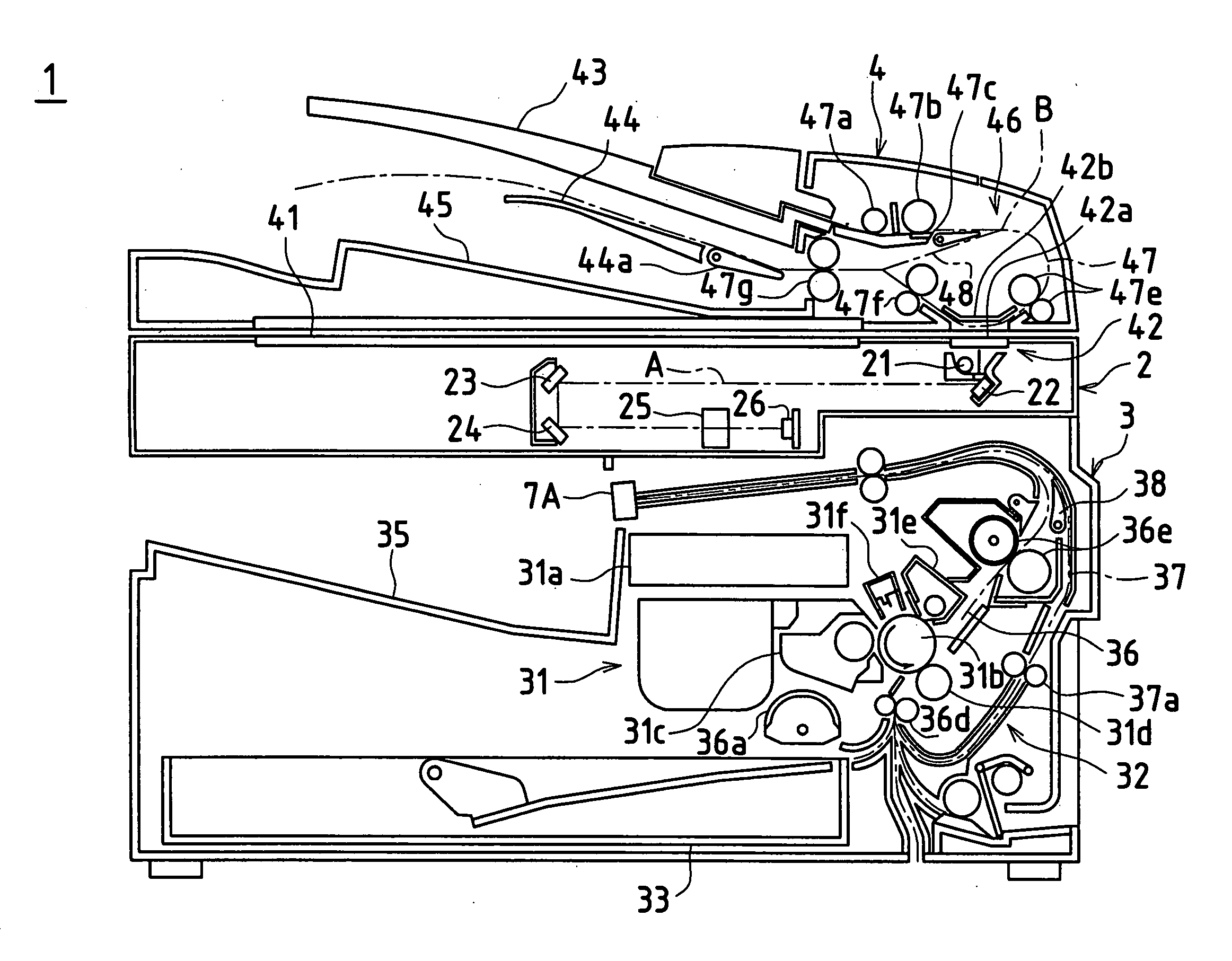
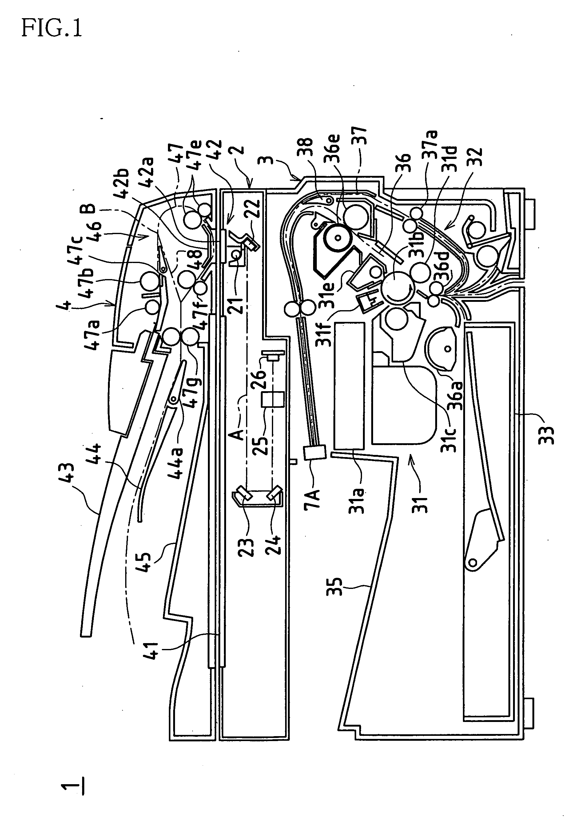
[0049]FIG. 1 schematically shows an overview of the internal structure of a compound machine 1 as an image forming apparatus according to the present embodiment. As shown in FIG. 1, the compound machine 1 includes a scanner portion 2, a print portion 3 as an image forming portion, and an automatic manuscript paper supply portion 4. These parts are described below.

2>

[0050] The scanner portion 2 reads the image of a manuscript placed on a manuscript rest 41 that is made of transparent glass, or the like, or the image of a manuscript that is supplied sheet by sheet from the automatic manuscript paper supply portion 4, and creates image data. This scanner portion 2 includes an exposure light source 21, a plurality of reflective mirrors 22, 23, and 24, an imaging lens 25, and a photoelectric transducer (CCD: Charge Coupled Device) 26.

[0051] The exposure light source 21 irradiates light onto the manuscript that is p...


PUM


Abstract

A discharge unit is disposed downstream of a principal transport path of a compound machine, and a shifter function is provided in this discharge unit. By shifting the paper passage position relative to a photosensitive drum when printing the front side and the paper passage position relative to the photosensitive drum when printing the back side, the region in which the surface electric potential of the photosensitive drum increases is diminished, and the region in which photographic fog is generated is made smaller. Thus, when printing the second and subsequent sheets, even when a slight amount of displacement of the transport position of the recording paper occurs, it is possible to suppress that recording paper making contact in the photographic fog region on the photosensitive drum, and defective printing can be prevented.

Description

TECHNICAL FIELD [0001] The present invention relates to an image forming apparatus. Specifically, the present invention relates to an approach for achieving an improvement in image quality in an image forming apparatus provided with a duplex printing function. BACKGROUND ART [0002] Conventionally, as an image forming (printing) operation in an electrophotographic image forming apparatus such as a laser printer, an electrostatic latent image is formed on a photosensitive drum based on image data sent from a host apparatus such as a personal computer (hereinafter, referred to as simply “PC”), toner is affixed to this electrostatic latent image, and image data is made manifest on the photosensitive drum. Afterwards, recording paper transported on a paper transport path is passed between the photosensitive drum and a transfer roller, and the toner image on the photosensitive drum is transferred to the front side of the recording paper. Then, this recording paper passes a fixing roller, ...

Claims


Application Information

Patent Timeline
Patent Type & Authority Applications(United States)
IPC IPC(8): G03G15/00G03G21/14B65H29/20G03G15/23G03G21/00
CPCG03G15/234
Inventor MURAKAMI, SUSUMUTOMIYORI, MINORUIZUMI, HIDESHINARIKIYO, TAKAHISANAKANO, KUNIAKIIWAKURA, YOSHIE
Owner SHARP KK
Why Eureka
Try Eureka