Four Component Phosphorescent OLED For Cool White Lighting Application

Active Publication Date: 2013-12-05
UNIVERSAL DISPLAY
View PDF8 Cites 94 Cited by
  • Summary
  • Abstract
  • Description
  • Claims
  • Application Information

AI Technical Summary

Benefits of technology

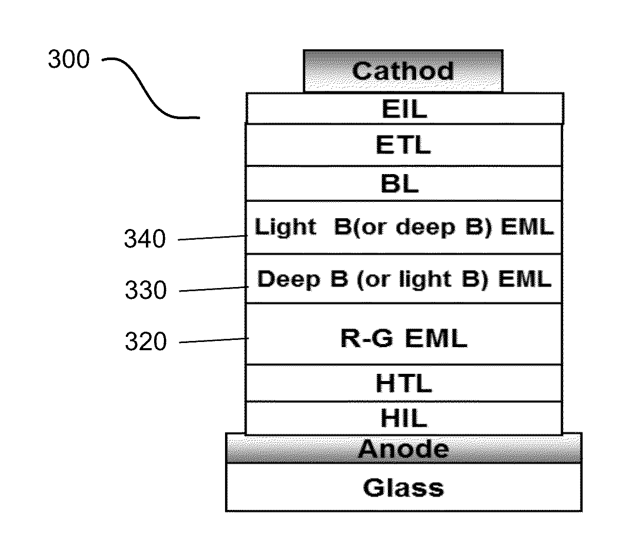
[0014]This present invention may find applicability in the field of cooler white lighting applications (i.e. a correlated color temperature or CCT>4500K). Cooler white OLED lighting is usually achieved in a stacked architecture by using fluorescent blue material whose efficiency is much lower than phosphorescent materials in general. In the present invention, a phosphorescent deep blue emitter may be applie

Problems solved by technology

The deep blue is usually less efficient and with shorter lif

Method used


Image

  • Four Component Phosphorescent OLED For Cool White Lighting Application
  • Four Component Phosphorescent OLED For Cool White Lighting Application
  • Four Component Phosphorescent OLED For Cool White Lighting Application

Examples


Example

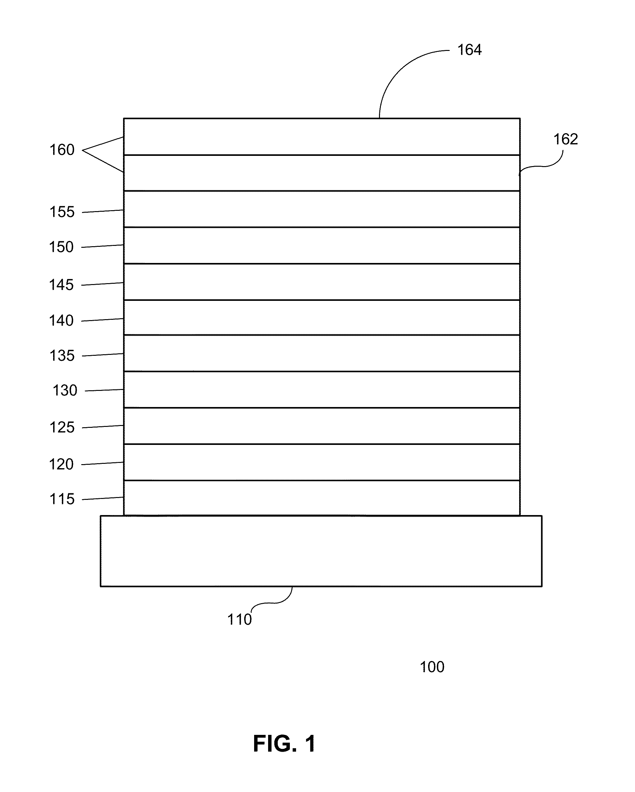
[0056]Generally, an OLED comprises at least one organic layer disposed between and electrically connected to an anode and a cathode. When a current is applied, the anode injects holes and the cathode injects electrons into the organic layer(s). The injected holes and electrons each migrate toward the oppositely charged electrode. When an electron and hole localize on the same molecule, an “exciton,” which is a localized electron-hole pair having an excited energy state, is formed. Light is emitted when the exciton relaxes via a photoemissive mechanism. In some cases, the exciton may be localized on an excimer or an exciplex. Non-radiative mechanisms, such as thermal relaxation, may also occur, but are generally considered undesirable.

[0057]The initial OLEDs used emissive molecules that emitted light from their singlet states (“fluorescence”) as disclosed, for example, in U.S. Pat. No. 4,769,292, which is incorporated by reference in its entirety. Fluorescent emission generally occur...


PUM


Abstract

A light emitting system is provided including a first organic light emitting device. The first organic light emitting device includes an anode, a cathode, a first organic emitting layer disposed between the anode and the cathode, and a second organic emitting layer disposed between the anode and the cathode. The first organic emitting layer and the second organic emitting layer each include an emissive dopant having a peak wavelength of between 400 to 500 nanometers, but one of the peak wavelength of one of the dopants is at least 4 nm less than the peak wavelength of the other dopant. The first organic emitting layer and the second organic emitting layer may overlap each other, such as being disposed one over the other. The device may be used in white light or multi-color systems.

Description

FIELD OF THE INVENTION[0001]The present invention relates to organic light emitting devices, and more specifically to the use of both light and deep blue organic light emitting compounds in a single device.BACKGROUND[0002]Opto-electronic devices that make use of organic materials are becoming increasingly desirable for a number of reasons. Many of the materials used to make such devices are relatively inexpensive, so organic opto-electronic devices have the potential for cost advantages over inorganic devices. In addition, the inherent properties of organic materials, such as their flexibility, may make them well suited for particular applications such as fabrication on a flexible substrate. Examples of organic opto-electronic devices include organic light emitting devices (OLEDs), organic phototransistors, organic photovoltaic cells, and organic photodetectors. For OLEDs, the organic materials may have performance advantages over conventional materials. For example, the wavelength ...

Claims


Application Information

Patent Timeline
IPC IPC(8): H05B33/14
CPCH05B33/145C09K2211/1007C09K2211/1029C09K2211/1044C09K2211/185H05B33/14H10K59/32H10K85/6576H10K85/6572H10K85/657H10K85/342H10K50/13H10K50/11H10K2101/10
Inventor WEAVER, MICHAELXU, XINBROWN, JULIA J.
Owner UNIVERSAL DISPLAY
Why Eureka
Try Eureka