
Image forming apparatus and method

a technology of image forming and forming apparatus, which is applied in the direction of inking apparatus, duplicating/marking methods, printing, etc., can solve the problems of affecting the output image with respect to the desired image, and affecting the quality of the image. , to achieve the effect of preventing the deterioration caused by the movement of the coloring material or the bleeding

Inactive Publication Date: 2009-09-10
FUJIFILM CORP
View PDF19 Cites 13 Cited by
  • Summary
  • Abstract
  • Description
  • Claims
  • Application Information

AI Technical Summary

Benefits of technology

[0009]The present invention has been contrived in view of the circumstances described above, an object thereof being to provide an image forming apparatus and an image forming method whereby, in a two-liquid aggregating system which uses ink and treatment liquid, an aggregating reaction of the ink on the recording medium can be carried out efficiently, and image deterioration caused by movement of the coloring material or bleeding can be prevented.
[0011]According to this aspect of the present invention, by suppressing the permeation of the treatment liquid deposited onto the recording medium while heating and drying the treatment liquid, it is possible reliably to form the solid or semi-solid aggregating treatment agent layer on the surface of the recording medium. By depositing droplets of the ink onto the recording medium on which the solid or semi-solid aggregating treatment agent layer has been formed, it is possible to achieve an efficient ink aggregating reaction on the surface of the recording medium, even in the case of high-speed droplet ejection with a droplet ejection interval of 10 to 50 microseconds, and hence it is possible to prevent image deterioration caused by movement of the coloring material or bleeding, and therefore an image of high quality can be formed.
[0018]According to this aspect of the present invention, by suppressing the permeation of the treatment liquid deposited onto the recording medium while heating and drying the treatment liquid, it is possible reliably to form the solid or semi-solid aggregating treatment agent layer on the surface of the recording medium. By depositing droplets of the ink onto the recording medium on which the solid or semi-solid aggregating treatment agent layer has been formed, it is possible to achieve an efficient ink aggregating reaction on the surface of the recording medium, even in the case of high-speed droplet ejection with a droplet ejection interval of 10 to 50 microseconds, and hence it is possible to prevent image deterioration caused by movement of the coloring material or bleeding, and therefore an image of high quality can be formed.

Problems solved by technology

However, the problem associated with the inkjet recording system is that where the adjacent ink droplets (dots) overlap to each other when the ink droplets are continuously deposited onto the recording medium, the so-called landing interference (bleeding) occurs, namely, the ink droplets forming the adjacent dots merge under the effect of surface tension on the recording medium and dots of desired shape and size cannot be formed.
As a result of this, a problem arises in that the output image is disturbed significantly with respect to the desired image.
Furthermore, if the treatment liquid permeates into the image receiving layer of the recording medium after the deposition of the treatment liquid on the recording medium and before the deposition of ink droplets, then a sufficient aggregating reaction does not occur on the surface of the recording medium, and hence there is also a problem in that a bleeding prevention effect is not obtained.
In particular, in a system where the deposition of the treatment liquid and the deposition of the ink droplets are performed by independent line heads, a time period of the order of several seconds is required from the deposition of the treatment liquid onto the recording medium until the deposition of the ink droplets, and hence a portion of the treatment liquid permeates into the recording medium and it is not possible to form an aggregating treatment liquid layer of sufficient volume on the surface of the recording medium.
Moreover, if ink droplets are continuously ejected at high speed in such a manner that a plurality of ink droplets are mutually overlapping on the recording medium (for example, at a droplet ejection interval of 10 to 50 microseconds), then the aggregating reaction of the ink droplets that have been previously deposited cannot proceed sufficiently rapidly, and bleeding occurs.

Method used


Image

  • Image forming apparatus and method
  • Image forming apparatus and method
  • Image forming apparatus and method

Examples


Embodiment Construction

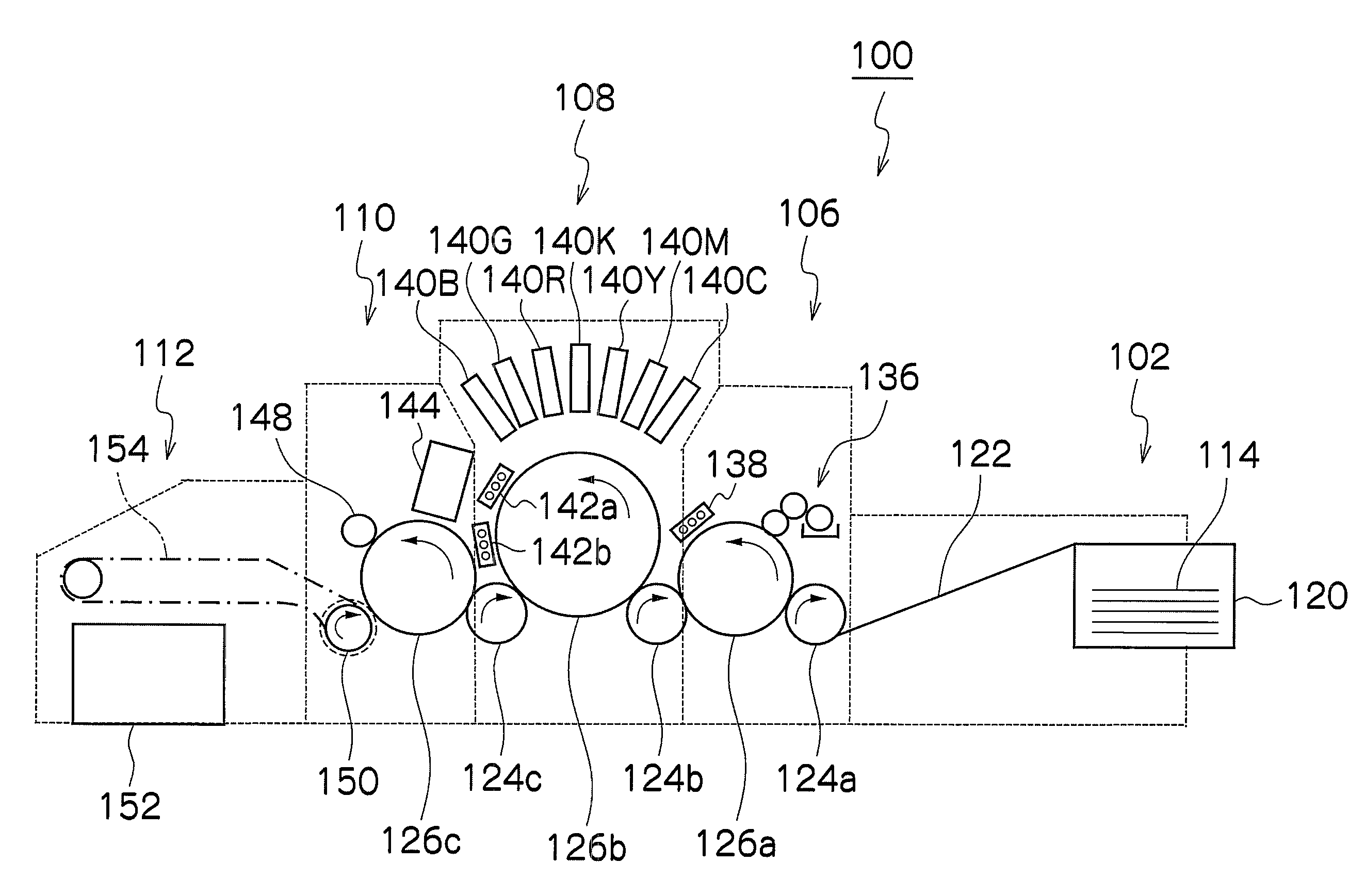
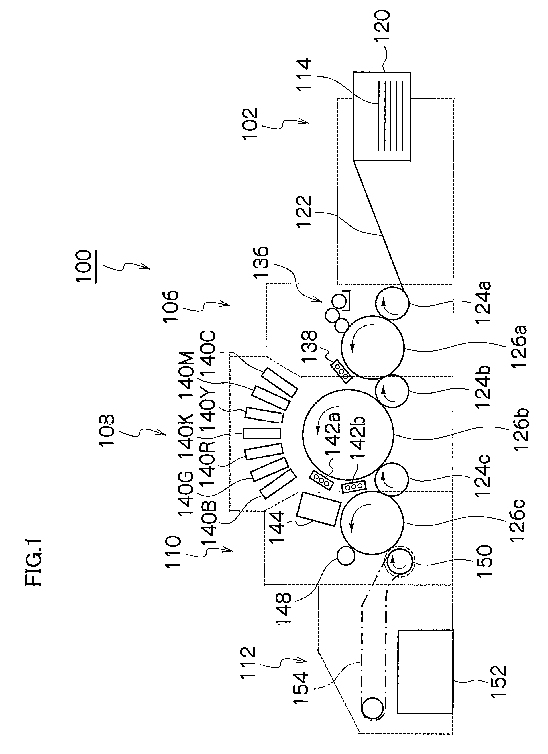
[0027]Firstly, the ink and the aggregating treatment liquid (hereinafter also referred to simply as “treatment liquid”) used in an embodiment of the present invention will be described, and then the image forming apparatus according to an embodiment of the present invention will be described.

Ink

[0028]The ink used in the present embodiment is water-based pigment ink that contains the following materials insoluble to the solvent (water): pigment particles as the coloring material, and polymer particles.

[0029]It is desirable that the concentration of the solvent-insoluble materials in the ink is not less than 1 wt % and not more than 20 wt %, taking account of the fact that the viscosity of the ink suitable for ejection is 20 mPa·s or lower. It is more desirable that the concentration of the pigment in the ink is not less than 4 wt %, in order to obtain good optical density in the image. It is desirable that the surface tension of the ink is not less than 20 mN / m and not more than 40 m...


PUM

PropertyMeasurementUnit
Fractionaaaaaaaaaa
Fractionaaaaaaaaaa
Fractionaaaaaaaaaa

Abstract

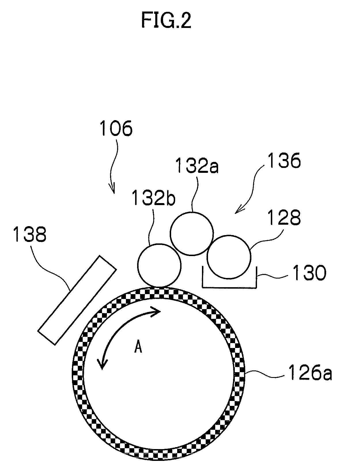
The image forming apparatus forms an image on a recording medium by using an ink and an aggregating treatment agent. The ink contains coloring material, and the aggregating treatment agent contains a component which causes the coloring material to aggregate. The image forming apparatus includes: a treatment liquid deposition device which deposits a treatment liquid onto the recording medium, the treatment liquid containing the aggregating treatment agent; a treatment liquid heating device which heats the treatment liquid having been deposited on the recording medium to form a solid or semi-solid layer of the aggregating treatment agent on the recording medium; a treatment liquid permeation suppression device which suppresses permeation of the treatment liquid into the recording medium at least from a time of deposition of the treatment liquid onto the recording medium until formation of the solid or semi-solid layer of the aggregating treatment agent; and an ink droplet ejection device which ejects and deposits droplets of the ink onto the recording medium on which the solid or semi-solid layer of the aggregating treatment agent has been formed.

Description

BACKGROUND OF THE INVENTION[0001]1. Field of the Invention[0002]The present invention relates to an image forming apparatus and an image forming method, and more particularly to an image forming apparatus and an image forming method in which an image is formed on an image formation body by using an ink and a treatment agent.[0003]2. Description of the Related Art[0004]In the inkjet recording system, the recording is performed by ejecting ink droplets onto a recording medium. By contrast with other systems, noise during the recording operation is low, running cost is low, and image recording with high resolution and high quality can be performed. The ink ejection system can be a piezoelectric system using the displacement of a piezoelectric element or a thermal system using thermal energy generated by a heat-generating element.[0005]However, the problem associated with the inkjet recording system is that where the adjacent ink droplets (dots) overlap to each other when the ink drople...

Claims


Application Information

Patent Timeline
IPC IPC(8): B41J2/01
CPCB41J2/14233B41J2/155B41J2202/20B41J11/002B41J2002/14459B41J11/0015B41J11/00222B41M5/0017
Inventor KUSUNOKI, NAOKI
Owner FUJIFILM CORP
Learn More