
Image forming apparatus featuring a changeable mixing ratio of deep and pale color toners

a technology of color toner and mixing ratio, which is applied in the direction of electrographic process apparatus, instruments, developers, etc., can solve the problems of image deterioration, transfer portion (transfer apparatus) being caused to occur in many, and deterioration of halftone image, etc., and achieves the effect of increasing the color density of toners

Inactive Publication Date: 2006-10-31
CANON KK
View PDF2 Cites 12 Cited by
  • Summary
  • Abstract
  • Description
  • Claims
  • Application Information

AI Technical Summary

Benefits of technology

[0012]An object of the present invention is to provide an image forming apparatus capable of preventing deterioration of an image, particularly a halftone image even in the case where the image is formed under a specific image forming condition such as a low humidity environment wherein image deterioration due to a discharge phenomenon in the vicinity of a transfer portion or at a portion downstream from the transfer portion is liable to occur.
[0017]In an embodiment of the image forming apparatus, an amount of a toner having a relatively low color density of the toners is increased when a humidity of the ambient environment or an absolute water (moisture) content of the transfer material is lower than a predetermined value.
[0021]wherein an amount of a toner having a relative low color density of the toners is increased when the transfer material has a thickness which is larger than a predetermined value.

Problems solved by technology

Generally, when a halftone image is formed in a low humidity environment, image deterioration due to a discharge phenomenon in the vicinity of the transfer portion (transfer apparatus) is caused to occur in many cases.
For this reason, deterioration of the halftone image has been caused to occur in some cases by discharge in the vicinity of the transfer portion particularly in a low humidity environment.

Method used


Image

  • Image forming apparatus featuring a changeable mixing ratio of deep and pale color toners
  • Image forming apparatus featuring a changeable mixing ratio of deep and pale color toners
  • Image forming apparatus featuring a changeable mixing ratio of deep and pale color toners

Examples


embodiment 1

(Embodiment 1)

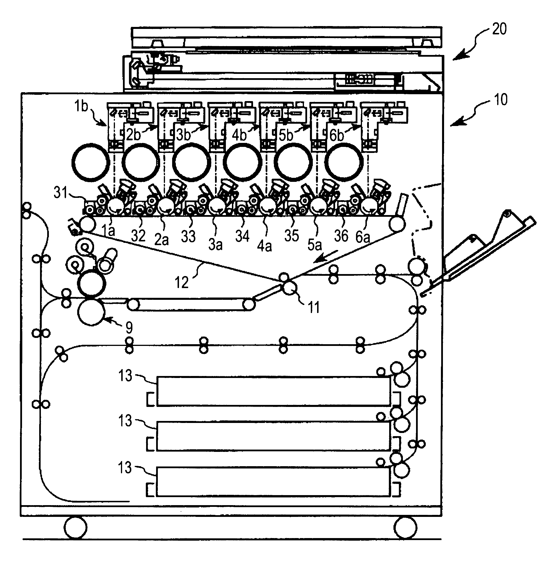
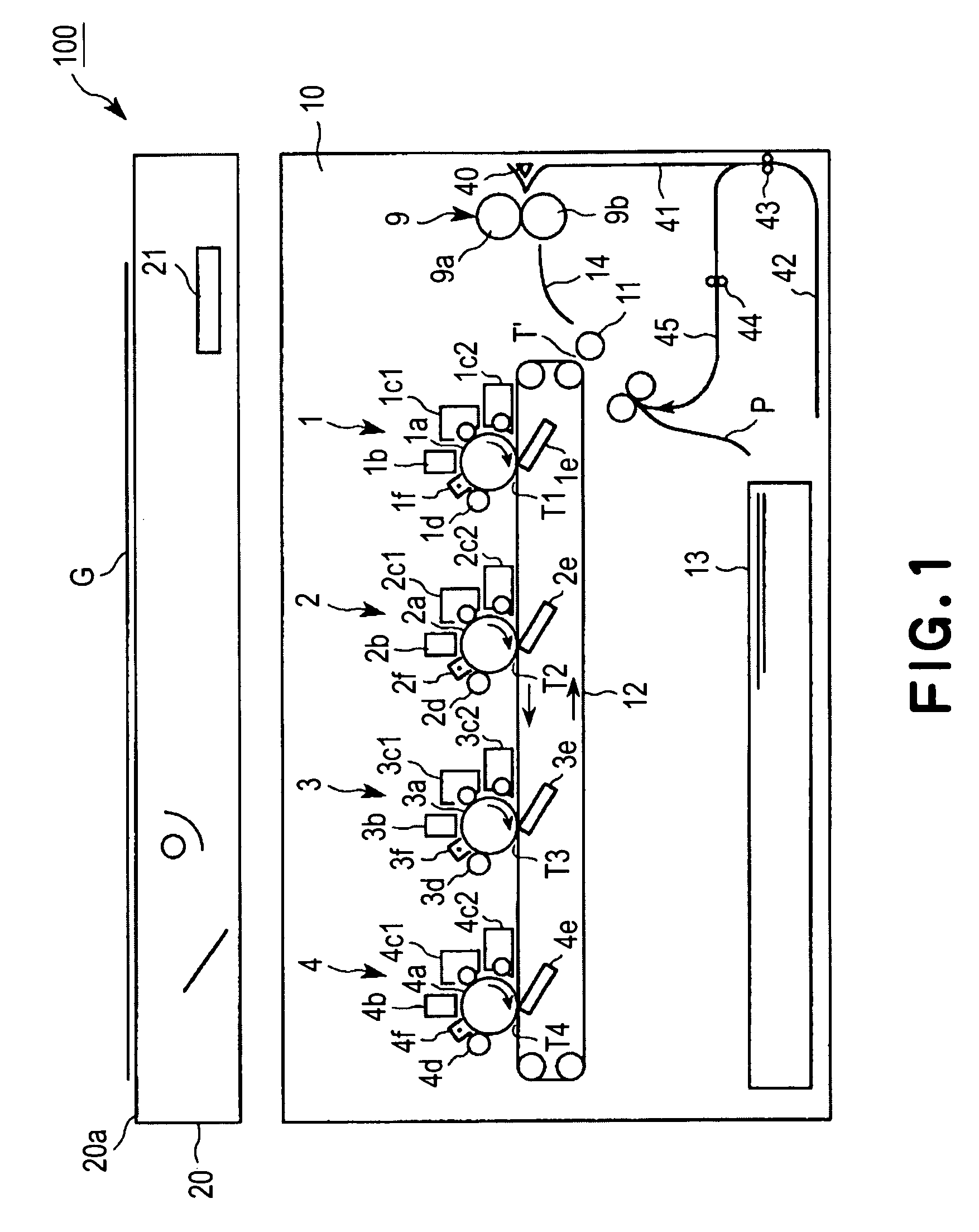
[0048]In this embodiment, an image forming apparatus 100 according to the present invention has a general structure shown in FIG. 1.

[0049]The image forming apparatus 100 can form a full-color image on a transfer material P, such as paper or an OHP sheet, in a printer unit 10 on the basis of an image information signal from a reader unit 20 or an external equipment, such as a personal computer, connected to a main assembly of the image forming apparatus so that the external equipment can communicate with the apparatus main assembly.

[0050]The image forming apparatus 100 of this embodiment includes four image formation 1 to 4, as a plurality of image forming means, which are juxtaposed with each other in series in a paper feed direction, as shown in FIG. 1. Each of the image formation stations 1 to 4 includes a cylindrical electrophotographic photosensitive member (photosensitive drum) 1a, 2a, 3a or 4a as an image bearing member; an exposure apparatus (laser scanning expo...

embodiment 2

(Embodiment 2)

[0100]An image forming apparatus used in this embodiment is identical to the image forming apparatus 100, used in Embodiment 1, described with reference to FIGS. 1 to 4.

[0101]In this embodiment, a maximum amount of toner is increased compared with that under the ordinary image forming condition by increasing the amounts of pale and deep color toners per unit area under a specific image forming condition.

[0102]As described in Embodiment 1, in the low humidity environment, it is preferable that the amount of toner per unit area is increased in order to suppress the image deterioration in the vicinity of the transfer portion.

[0103]Further, generally, in order to prevent winding of the transfer material P due to adhesive force between the toner image and the fixing member in the fixing apparatus 9, an upper limit of the amount of toner per unit area is set to a certain value. However, in the low humidity environment, the winding of the transfer material P in the fixing app...

embodiment 3

(Embodiment 3)

[0109]In the above-described Embodiments 1 and 2, as the specific image forming condition such that the image deterioration due to the discharge phenomenon in the vicinity of the transfer portion is liable to occur, the low humidity environment is employed but such a specific image forming condition is not limited thereto.

[0110]For example, the specific image forming condition may be a water (moisture) content of the transfer material. This is because, similarly as in the case of the temperature and humidity of ambient environment, the discharge phenomenon is liable to occur n the vicinity of the transfer portion when the water content is low. In this case, as a detection means of the image forming condition, for example, a means for detecting the water content of the transfer material by measuring an electric resistance of the transfer material or a means for detecting the water content of the transfer material on the basis of an infrared absorptance is provided so as...


PUM


Abstract

An image forming apparatus includes image forming means for forming a superposed image on an image bearing member by using at least toners which have an identical hue and different color densities; transfer means for electrostatically transferring the superposed image on the image bearing member onto a transfer material; and changing means for changing a mixing ratio between the toners which have an identical hue and different color densities depending on information on a water content of the transfer material, thereby to prevent a deterioration of an image, particularly a halftone image even in the case where the image is formed under a specific image forming condition, such as in a low humidity environment, liable to cause image deterioration due to a discharge phenomenon in the vicinity of a transfer portion.

Description

[0001]This application claims priority from Japanese Patent Application No. 205388 / 2003 filed Aug. 1, 2003, which is hereby incorporated by reference.FIELD OF THE INVENTION AND RELATED ART[0002]The present invention relates to an image forming apparatus utilizing an electrophotographic process or an electrostatic recording process, such as a copying machine or a printer. More specifically, the present invention relates to an image forming apparatus employing a combination of toners which have an identical hue and different color densities.[0003]At present, a full-color image forming apparatus including a developing apparatus using toners of four colors of yellow, magenta, cyan and black has been generally used.[0004]For example, as described in Japanese Laid-Open Patent Application (JP-A) No. 2000-231279, an image forming apparatus using a combination of a plurality of toners which have an identical hue and are different in depth of a color, has been proposed. The image forming appa...

Claims


Application Information

Patent Timeline
Patent Type & Authority Patents(United States)
IPC IPC(8): G03G15/00G03G9/09G03G15/01G03G15/043G03G15/08G03G21/00
CPCG03G15/0131G03G15/043G03G15/0822G03G2215/00776G03G2215/0429
Inventor MOCHIZUKI, JUN
Owner CANON KK
Learn More